Nozzle Impact Resistance Test Apparatus for Mechanical Strength and Product Quality Evaluation
1. Introduction: Why Nozzle Impact Resistance Testing Matters
In many industrial applications, a nozzle is expected to maintain its shape, strength, and working performance even when it experiences accidental knocks during handling, transportation, installation, or use. A small impact may look harmless from the outside, but it can damage a thin wall, deform a discharge opening, loosen an internal component, or affect the way a fluid or spray is delivered. For manufacturers, understanding these risks before a product reaches the market is an important part of product development and quality control.
At Guangzhou Chuangge Automation Equipment Co., Ltd., we specialize in customized industrial testing equipment. We work with customers who need practical ways to evaluate material strength, product durability, and performance under defined test conditions. Our Nozzle Impact Resistance Test Apparatus is intended for applications where a nozzle or nozzle assembly needs to be subjected to a controlled mechanical impact and then examined according to a specified testing procedure.
The purpose of an impact resistance test is straightforward: apply a defined impact to a test specimen, observe what happens, and determine whether the specimen continues to meet the relevant requirements. Depending on the nozzle design and the applicable method, the evaluation may include visual inspection, dimensional checks, leakage testing, connection checks, or a functional test after impact.
However, not every nozzle is designed for the same working conditions. A fire-protection nozzle, a water-mist nozzle, a fuel-dispensing nozzle, and an industrial spray nozzle may have very different structures and safety requirements. Their impact tests can differ in specimen orientation, impact location, energy, number of impacts, conditioning, and post-test inspection. A test arrangement suitable for one type of nozzle should not automatically be applied to another.
That is why we approach the Nozzle Impact Resistance Test Apparatus as a customized testing solution rather than a machine with one universal set of parameters. Before confirming a configuration, we need to understand the product, the purpose of the test, the relevant standard or internal procedure, and the results the customer needs to record.
Our company serves a wide range of industrial testing applications, including construction materials and components, wires and cables, plastics and textiles, electrical plugs, sockets and switches, electronic products, and household appliances. We have obtained ISO 9001 quality management, ISO 14001 environmental management, and ISO 45001 occupational health and safety management certifications. Our intellectual property portfolio includes more than 20 patents covering invention, utility model, and software categories.
For nozzle manufacturers, testing laboratories, and quality inspection teams, our goal is to help translate a test requirement into a workable equipment configuration. We focus on clear technical communication, practical operation, and a defined inspection scope so that the customer understands what the equipment is designed to do.
2. How a Nozzle Impact Resistance Test Apparatus Works
2.1 The basic principle of impact resistance testing
An impact test exposes a specimen to a mechanical force over a relatively short period. Unlike a slow compression test, in which a load is gradually increased, an impact test examines how a product responds to a sudden contact or collision. The test may use a falling mass, a pendulum, a guided impactor, or another arrangement specified by the relevant method.
For a nozzle impact resistance test, the specimen is secured in a defined position, and the impact is applied at the specified location and direction. The impact energy, impactor geometry, specimen support, and release or driving mechanism all affect the result. If any of these conditions change significantly between tests, the results may no longer be directly comparable.
Impact energy is commonly expressed in joules (J). For a falling mass, the theoretical gravitational potential energy before release can be calculated as:
E = m × g × h
In this formula, E is potential energy in joules, m is the mass in kilograms, g is gravitational acceleration in metres per second squared, and h is the vertical drop height in metres. This relationship is useful when planning a falling-mass test, but it does not by itself establish the impact energy transferred to the specimen. Friction, impact geometry, deformation, and other factors can influence the actual event.
For a pendulum system, impact energy is associated with the change in gravitational potential energy between the release position and the impact position. The required pendulum geometry and energy calculation must follow the chosen test design. We therefore confirm the impact mechanism and required energy with the customer instead of assuming that every Nozzle Impact Test uses a falling weight.
2.2 A typical testing sequence
The operating sequence depends on the machine configuration and the applicable procedure. In a typical project, the operator first checks the specimen and records its identification. The specimen is then mounted in the required position, and the impact parameters are checked before the test begins.
The apparatus applies the specified impact. After the impact, the operator examines the specimen for visible damage and carries out any additional checks required by the test method. If the nozzle is intended to carry fluid, for example, the procedure may require a leakage or functional check after the mechanical test. A visual inspection alone may not be sufficient to establish that the product remains fit for use.
| Test stage | Typical activity | Purpose |
|---|
| Specimen identification | Record model, batch, material, dimensions, and relevant product details. | Maintain traceability between the test result and the specimen. |
| Pre-test inspection | Check for existing cracks, deformation, loose parts, or visible defects. | Distinguish pre-existing damage from damage caused by the test. |
| Mounting and alignment | Secure the specimen and confirm the required impact position and direction. | Help ensure consistent test conditions. |
| Impact application | Apply the specified impact using the agreed mechanism and settings. | Expose the specimen to the defined mechanical event. |
| Post-test inspection | Inspect the body, connection points, discharge section, and other relevant features. | Identify damage or changes that may affect use. |
| Follow-up verification | Carry out leakage, dimensional, or functional checks when required. | Determine whether the specimen still meets the relevant requirements. |
| Result recording | Document test conditions, observations, measurements, and outcomes. | Support comparison, quality analysis, and technical review. |
This table describes a general workflow, not a universal standardized procedure. The exact number of specimens, impact energy, impact location, conditioning, acceptance criteria, and follow-up tests must be taken from the relevant standard or customer-approved test plan.
2.3 Why specimen mounting is important
Mounting may appear to be a simple detail, but it can have a major effect on impact test results. If a nozzle is held too loosely, it may move away from the impactor and absorb less energy than expected. If it is clamped in a way that is not permitted by the test method, the support may change the way the product deforms.
The fixture should hold the specimen in the prescribed position without introducing an unintended restraint. For a threaded nozzle, the mounting may need to represent a defined installation condition. For a nozzle with a projecting deflector or cap, the fixture may need to provide clearance so that the impact occurs at the intended point. The correct arrangement depends on the product design and test procedure.
We recommend that customers provide engineering drawings, photographs, dimensions, mounting details, and information about the intended impact location before equipment design begins. If the product has several variants, we can discuss interchangeable fixtures or separate mounting arrangements as part of the customization process.
2.4 What should be checked after the impact?
The answer depends on what the nozzle is designed to do. For a simple mechanical component, the test may focus on cracks, deformation, detachment, or changes in dimensions. For a nozzle that carries water, fuel, gas, or another fluid, mechanical damage may also affect sealing, flow, connection security, or the ability to operate normally.
For that reason, impact resistance should not always be judged by appearance alone. A nozzle may look undamaged while a seal has shifted or a connection has been weakened. Where the relevant method requires a leakage test or functional verification after impact, that follow-up step is an essential part of the overall evaluation.
Our equipment scope can be discussed around the required impact application and any agreed supporting functions. If a customer needs a complete post-impact leakage or flow test, we must clarify whether that function is integrated into the project or carried out using separate equipment.
3. Main Features and Customization Options
3.1 An impact mechanism selected for the test method
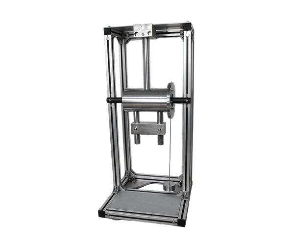
There is no single impact mechanism that suits every nozzle. Depending on the test requirement, a machine may use a guided falling mass, a pendulum impactor, or another controlled arrangement. The selected mechanism must be compatible with the required impact energy, impact direction, available space, and specimen geometry.
A falling-mass arrangement can be suitable when a test method defines an impact based on a mass and drop height. A pendulum arrangement may be appropriate when the procedure defines impact energy through a swinging impactor. Other configurations may be necessary for products with special mounting conditions or impact points.
We determine the suitable arrangement after reviewing the customer's method. We do not assume that one mechanism is suitable for every product or that a machine can reproduce a standardized test simply because it can deliver an impact. The complete arrangement—including the impactor, specimen support, alignment, and safety features—must match the intended test.
3.2 Adjustable specimen fixtures
Nozzles vary considerably in length, diameter, connection type, body shape, and the position of the vulnerable features. A fixture designed around one nozzle may not be suitable for a different model. For manufacturers testing several product families, fixture flexibility can be a practical consideration.
Depending on the agreed design, we can discuss dedicated fixtures, interchangeable holders, adjustable supports, and arrangements that make specimen positioning easier. These options need to be evaluated against the test method. An adjustable fixture is useful only when it can hold the specimen securely and reproduce the required mounting conditions.
For customized equipment, the most useful information includes maximum and minimum specimen dimensions, thread or connection details, the intended mounting orientation, the location of the impact, and the clearance needed around the specimen. If the product has delicate parts or a special surface finish, that should also be explained during the design stage.
3.3 Controlled and repeatable impact application
Repeatability means that the same test arrangement can be used consistently so that differences between specimens are less likely to come from avoidable changes in the equipment setup. For an impact test, important factors include the impactor mass and shape, release position, impact direction, mounting rigidity, and the way the specimen is positioned.
Where appropriate, the apparatus can be designed to support consistent release or movement of the impact mechanism. The exact control method depends on the required procedure and the agreed equipment configuration. If the method calls for a manually released mass, the machine should support that arrangement safely and consistently rather than adding unnecessary automation.
Repeatability also depends on the operator and the specimen itself. A clear operating procedure, regular inspection, proper mounting, and complete records all help reduce variation. Equipment design and laboratory procedure should therefore be treated as parts of the same testing process.
3.4 Safety and operator protection
Impact testing involves moving masses or impactors, so the design needs to consider the risk of pinch points, rebound, falling components, and fragments from a damaged specimen. The appropriate safeguards depend on the impact mechanism, energy level, specimen material, and working environment.
Potential design considerations include a stable frame, secure specimen mounting, guarding around the impact zone, a controlled release mechanism, clear operating instructions, and measures to prevent unintended movement. Where a specimen may fracture, the need for a protective enclosure or other containment measures should be evaluated as part of the risk assessment.
We discuss these points during project planning. The final safety features must be confirmed in the technical specification, and the equipment should be installed and operated according to the supplied instructions and the customer's local safety procedures.
3.5 Measurement, inspection, and data records
Some impact tests require only a defined mechanical event followed by visual inspection. Others require the impact energy to be set or verified, dimensions to be measured, or follow-up leakage and functional checks to be documented. The necessary instrumentation depends on the method.
Where required, the equipment design can be discussed in relation to impact energy settings, position references, test counters, operator prompts, or data recording. These are configuration options, not features that should be assumed to come with every apparatus. The customer should identify the records required by the quality system, laboratory procedure, or customer specification.
A useful record may include the specimen model, batch number, test date, impact position, selected parameters, operator, visual observations, and the results of any follow-up checks. If a test fails, a detailed record helps the technical team determine whether the problem may relate to the product, the mounting, the impact conditions, or another factor.
3.6 Summary of important configuration choices
| Configuration area | Information to confirm | Why it matters |
|---|
| Impact mechanism | Required impact method, energy, direction, and impactor geometry. | Determines how the mechanical event is applied. |
| Specimen fixture | Dimensions, connection type, mounting orientation, and impact location. | Helps reproduce the specified test arrangement. |
| Impact settings | Mass, height, pendulum position, or other method-specific parameters. | Supports controlled testing and comparison. |
| Safety arrangements | Moving parts, rebound risks, specimen fracture risks, and operator access. | Helps reduce hazards during testing. |
| Post-impact checks | Visual inspection, dimensional measurement, leakage, or functional tests. | Defines how damage and performance changes are evaluated. |
| Data and documentation | Required fields, report format, record storage, and traceability needs. | Supports quality review and later investigation. |
The table summarizes common design considerations. The actual machine scope is established through technical discussion and documented in the final quotation or specification.
4. Standards and Test Method Selection: Avoiding the Wrong Test Setup
4.1 Why the product category matters
The term “nozzle” covers many different products. A nozzle may be part of a fire-protection system, a water-mist system, a vehicle refuelling connection, an industrial spray line, or another fluid-handling application. These products do not necessarily share the same impact test method or acceptance criteria.
For example, EN 17450-2:2024 covers product requirements and test methods for water mist nozzles. Its contents identify resistance to impact as a separate characteristic, alongside other tests such as mechanical strength, leak resistance, vibration resistance, and thermal response. This is an important reminder that impact resistance is only one part of a broader product evaluation when that standard applies.
The standard's scope and test clauses must be checked before an apparatus is specified. A water-mist nozzle test cannot automatically be used as the basis for a fuel-dispensing nozzle, and a method written for one class of fire-protection product may not apply to another.
For products in other categories, the relevant standard may be different. ISO 21058:2019, for example, addresses compressed or liquefied dimethyl ether (DME) refuelling connectors for road vehicles and includes an impact-resistance procedure for the nozzle. Its test arrangement and post-impact requirements are specific to that application. It should not be treated as a general nozzle standard.
4.2 Examples of how impact procedures can differ
Different methods may specify different impact mechanisms, conditioning conditions, impact locations, numbers of impacts, and follow-up checks. Even when two tests both use the term “impact resistance,” they may be measuring performance under substantially different conditions.
| Reference or test category | Relevant focus | What equipment planning should consider |
|---|
| EN 17450-2:2024 | Requirements and test methods for water mist nozzles, including resistance to impact. | Confirm the applicable nozzle type, exact clause, specimen setup, impact method, and required post-test checks. |
| ISO 21058:2019 | DME refuelling connectors for road vehicles, including nozzle impact resistance. | Confirm the specified conditioning, drop procedure, working-pressure conditions, connection checks, and leakage requirements. |
| Customer-specific internal method | Evaluation of a particular nozzle design or production quality requirement. | Document the impact energy, location, direction, mounting, specimen count, and acceptance criteria. |
Source notes for Table 2: The scope and topics are based on the published information for EN 17450-2:2024 and ISO 21058:2019. These references are examples of application-specific procedures, not interchangeable test methods. Consult the full applicable standard and confirm its current status before specifying equipment.
4.3 Impact energy alone does not define the test
It is tempting to compare impact test machines by looking only at their energy rating. That is not enough. Two machines may apply the same nominal energy but use different impactor shapes, contact points, mounting arrangements, or movement paths. Those differences can change the local stress and the way the specimen responds.
Consider a nozzle body with a projecting deflector. An impact applied to the main body may produce a different result from an impact applied to the deflector. Likewise, a nozzle mounted rigidly in a fixture may respond differently from a product tested in a prescribed installed condition. The correct setup is the one defined by the relevant method, not simply the one that delivers a particular energy value.
For this reason, we recommend that customers provide the full test procedure or the relevant clauses whenever possible. If the method is an internal company procedure, the customer should define the required parameters and pass/fail criteria clearly. We can then assess the equipment configuration against those requirements.
4.4 Post-impact performance can be just as important as visible damage
A nozzle may pass a visual inspection and still fail a later functional check. For products that handle fluid under pressure, an impact could damage a sealing surface, weaken a threaded connection, or alter an internal passage. The appropriate post-test checks depend on the product's purpose and the applicable requirements.
The published test information for ISO 21058:2019, for example, describes impact testing of DME refuelling nozzles followed by checks that include normal connection and disconnection and compliance with specified leakage requirements. This illustrates why the acceptance process may include more than looking for cracks or deformation.
For water mist nozzles, EN 17450-2:2024 includes a dedicated impact-resistance test within a larger set of product tests. The actual procedure and acceptance requirements should be taken from the complete standard. We do not assume that a single impact test result establishes overall nozzle performance or product conformity.
4.5 What to prepare before requesting a quotation
To help us identify a suitable Nozzle Impact Resistance Test Apparatus, customers should prepare the product model, drawings, dimensions, material, connection type, intended application, and the required impact location. If a standard applies, provide its designation, edition, and relevant clause. It is also useful to explain whether the specimen must undergo pressure, leakage, flow, or functional checks after impact.
For an internal test method, the required impact energy, mass or impactor geometry, drop height or pendulum settings, number of impacts, specimen orientation, and acceptance criteria should be defined as clearly as possible. Where the method is still being developed, the customer should identify which parameters are fixed and which remain open for technical discussion.
We can then review the requested test scope, identify the equipment functions needed, and discuss whether post-impact checks should be integrated into the project or performed separately. This approach helps avoid over-specifying the equipment or leaving an important part of the test process out of the final design.
5. Applications in Manufacturing, Quality Control, and Product Development
5.1 Nozzle manufacturers
For nozzle manufacturers, impact resistance testing can support product development, design verification, production quality control, and failure investigation. During development, engineers may compare different body designs, wall thicknesses, materials, mounting features, or protective structures. A defined test procedure provides a consistent way to observe how the variants respond to impact.
In production, manufacturers may use impact tests to check samples from selected batches or to investigate a change in material or manufacturing process. The test plan should specify how samples are selected and what constitutes an acceptable result. Without clear sampling rules and acceptance criteria, test results may be difficult to interpret consistently.
If an unexpected failure occurs, records of the impact conditions and specimen details can help the engineering team investigate the cause. For example, a crack near a connection may require a different review from deformation of a projecting component. The result should be considered alongside dimensional inspection, material information, production history, and other relevant tests.
5.2 Fire-protection and water-mist equipment
Fire-protection components may be expected to remain mechanically sound through handling and installation, and they must function as intended in the system for which they were designed. For water-mist nozzles, impact resistance is one of several characteristics that may be evaluated under an applicable product standard.
A nozzle's ability to withstand impact does not by itself demonstrate that it provides the required spray pattern, flow rate, thermal response, or fire-suppression performance. Those characteristics may require separate tests. The impact apparatus should therefore be viewed as one part of the product testing process rather than a replacement for all other evaluations.
For fire-safety equipment manufacturers, the best configuration depends on the specific nozzle family and the certification or verification route being followed. If the equipment will support a formal conformity assessment, the intended laboratory or certification organization should confirm the applicable test requirements before the apparatus is finalized.
5.3 Fluid-handling and refuelling equipment
Nozzles used in fluid-handling applications may need to maintain connection integrity and sealing performance after mechanical shock. The exact risks depend on the medium, working pressure, connection design, and intended environment.
In these applications, impact testing may be followed by leakage checks, connection operation checks, or other inspections. A suitable test plan should make clear whether the nozzle is tested empty or under a defined pressure condition, whether temperature conditioning is required, and what follow-up checks are mandatory.
Where flammable or pressurized media are involved, the test setup also requires careful consideration of safety. The test method, specimen conditioning, pressure arrangements, containment, and handling procedures must be appropriate to the product and the facility. The impact apparatus should not be used with hazardous media unless the complete setup has been specifically designed and approved for that use.
5.4 Industrial spray and process nozzles
Industrial spray nozzles are used in applications such as cleaning, coating, cooling, lubrication, and process-fluid delivery. Their performance may depend on a carefully formed opening, internal passage, or spray-forming component. An impact can affect those features even if the outer body shows little visible damage.
A manufacturer may therefore choose to combine impact resistance testing with dimensional inspection or a functional spray check. Whether such checks are necessary depends on the product's intended use and the customer's quality requirements. If the nozzle's performance is defined by flow rate, spray angle, or distribution, those measurements should be specified separately from the mechanical impact procedure.
We can discuss customized fixtures and impact arrangements for industrial nozzle shapes, but the scope must be defined from the product drawing and test objective. We do not assume that every industrial spray nozzle uses the same acceptance limits or can be evaluated by one universal impact method.
5.5 Laboratories, inspection departments, and research teams
Testing laboratories and internal inspection departments need results that can be traced to the specimen and the method used. A well-planned apparatus can make it easier to repeat the impact conditions, position specimens correctly, and record the observations required by the test plan.
Research teams may also use impact testing to compare prototypes or investigate a product failure. In research work, it can be useful to vary one parameter at a time, such as the impact location or the specimen design, while keeping other conditions controlled. This makes it easier to understand which changes may be associated with the observed outcome.
Exploratory testing should be distinguished from standardized conformity testing. A test designed to compare prototypes may be useful for engineering decisions, but it does not automatically satisfy a product standard or support a formal certification claim. The method and the intended use of the results should always be stated clearly.
6. Our Customization Process, Quality Checks, and Delivery
6.1 We begin with the customer's test requirements
At Guangzhou Chuangge Automation Equipment Co., Ltd., we start a customized equipment project by understanding the test that the customer needs to perform. For a Nozzle Impact Resistance Test Apparatus, the first questions concern the product, the intended impact, and the evaluation criteria. These details guide the design far more effectively than the equipment name alone.
During the initial discussion, we may ask for the following information:
Product model, engineering drawing, material, dimensions, and connection details.
The intended use of the nozzle and the mechanical risks the test needs to evaluate.
The applicable standard, edition, relevant clause, or internal test procedure.
Impact energy, impactor geometry, impact direction, location, and number of impacts.
Specimen mounting conditions, fixture requirements, and sample quantity.
Required pre-test conditioning and post-impact inspection or functional checks.
Safety requirements, operating environment, installation space, and available utilities.
Data recording, documentation, acceptance checks, packaging, and delivery requirements.
Drawings and reference procedures are especially useful for non-standard specimens. If a requirement is unclear, we can identify the information that still needs confirmation before manufacturing begins. If the project involves a certification body or external testing laboratory, the customer should confirm the applicable method with that organization before finalizing the equipment specification.
6.2 Design and manufacturing considerations
After the technical requirements are reviewed, the equipment design can address the impact mechanism, specimen fixture, supporting structure, operating controls, guarding, and any required measurement or recording functions. The design needs to consider not only the impact event itself but also the operator's workflow and the practical conditions in which the machine will be installed.
The fixture must hold the specimen in the required position without interfering with the intended impact. The impactor must be suitable for the specified contact geometry. The operating mechanism should allow the required impact condition to be applied consistently. Where the test involves a falling mass or moving pendulum, the structure and safety measures must be appropriate for the moving components and the intended energy level.
We confirm the agreed configuration before production. If the customer needs additional functions, such as test counting, electronic data recording, or an integrated follow-up check, those requirements should be stated in the technical specification. They should not be assumed to be included unless they have been agreed.
6.3 Pre-delivery inspection and functional verification
Before delivery, each unit undergoes functional inspection and performance verification according to the agreed project scope. The checks depend on the equipment design and may cover the impact mechanism, release or movement functions, specimen fixture, control interface, safety arrangements, and other configured functions.
Where the project requires verification of a specific impact energy or measurement function, the method and acceptance criteria should be agreed before manufacturing is completed. The customer should also identify whether any special records, measurement certificates, or third-party verification are required.
Functional inspection confirms that the specified equipment functions have been checked within the agreed scope. It is not automatically equivalent to accredited calibration, third-party certification, or a declaration that the apparatus complies with every clause of a particular standard. If a project requires those services or documents, the requirements and responsibilities must be defined separately.
6.4 Documentation and customer support
We provide technical documentation as agreed for the order. Depending on the project scope, this may include equipment information, operating instructions, maintenance guidance, electrical documentation, and records from pre-delivery inspection. Customers should communicate any required document format or internal quality-system requirement before the equipment is manufactured.
Clear documentation is useful for operator training, routine checks, troubleshooting, and future maintenance. It also helps the customer understand the intended operating sequence and the limits of the equipment. If the machine is configured for a particular test method, the agreed method and parameters should be identified in the documentation wherever appropriate.
6.5 Production lead time, payment, and transportation
Our typical production cycle for customized testing equipment is approximately 30 to 60 days. The actual lead time depends on the equipment specifications, the degree of customization, component availability, design confirmation, and any special inspection or documentation requirements.
Payment terms are negotiable and can be discussed according to the project and order conditions. We recommend confirming the technical scope, payment schedule, delivery timeline, and acceptance requirements in the quotation or contract before production begins.
We can arrange shipment by sea, air, or land according to the destination, delivery schedule, and equipment requirements. Protective packaging is selected to reduce the risk of movement, impact damage, and environmental exposure during transportation. Sturdy wooden cases may be used where appropriate for the equipment size and shipping conditions.
To help us plan the shipment, customers should provide the delivery destination, unloading arrangements, site access information, and any special transport or customs documentation requirements. Early confirmation makes it easier to select suitable packaging and avoid unnecessary delays.
7. Why Choose Guangzhou Chuangge Automation Equipment Co., Ltd.?
7.1 Customized equipment based on real applications
Different customers can use the same equipment name to describe very different testing requirements. One manufacturer may need a simple mechanical impact test, while another may require a specific mounting condition and a leakage check after impact. We believe the equipment should be designed around the actual test requirement rather than a generic description.
For the Nozzle Impact Resistance Test Apparatus, this means confirming the nozzle type, impact mechanism, test parameters, specimen fixture, safety needs, and required output records. By clarifying these points early, we can work toward a configuration that fits the customer's application and avoids unnecessary functions.
7.2 Experience across industrial testing equipment
Our products are used in a variety of industrial sectors, including construction materials and components, wires and cables, plastics and textiles, electrical plugs, sockets and switches, electronic products, and home appliances. These applications require different sample fixtures, test methods, measurement arrangements, and quality procedures.
This experience supports our approach to requirement analysis and equipment customization. We understand that a useful test machine must be practical for the people who operate it, compatible with the intended specimen, and clearly defined in terms of its functions. For specialized nozzle testing, we work from the customer's technical information to identify the appropriate equipment arrangement.
7.3 Quality management and intellectual property
Guangzhou Chuangge Automation Equipment Co., Ltd. has obtained ISO 9001 quality management, ISO 14001 environmental management, and ISO 45001 occupational health and safety management certifications. These certifications relate to the company's management systems in their respective areas; they should not be interpreted as automatic certification of a particular testing machine or of the customer's nozzle product.
Our intellectual property portfolio includes more than 20 patents across invention, utility model, and software categories. Our corporate philosophy is to ensure survival through high technology and drive development through high quality. We apply this philosophy by focusing on practical engineering, clear requirements, and a defined scope for each customized project.
7.4 Clear technical communication
Customized equipment projects can become difficult when important requirements are left until late in the process. Questions about the impact method, specimen support, energy settings, safety features, and post-test checks can affect the machine design. We therefore encourage customers to share the relevant technical documents and clarify their intended acceptance criteria early.
When the test method is not yet finalized, we can help identify the equipment-related questions that need to be resolved. However, the applicable standard and formal acceptance criteria must be confirmed from the relevant technical documents and, where necessary, with the responsible testing or certification organization.
Our aim is to deliver a practical testing solution with agreed functions, clear operating information, and an inspection scope that the customer understands. That is a more reliable basis for cooperation than promising universal compliance without first reviewing the product and test requirements.
8. Frequently Asked Questions About Nozzle Impact Resistance Test Apparatus
Q1. What is a Nozzle Impact Resistance Test Apparatus used for?
It is used to apply a defined mechanical impact to a nozzle or nozzle assembly so that the specimen's response can be evaluated. Depending on the test method, the evaluation may include visual inspection, dimensional checks, leakage testing, connection checks, or functional verification after impact.
Q2. Can the apparatus test every type of nozzle?
Not automatically. Nozzles differ in shape, material, connection design, intended medium, and applicable test requirements. The impact mechanism and fixture must be suitable for the particular specimen and test method. We recommend providing drawings and the relevant test procedure before confirming the equipment configuration.
Q3. Which standards can be used for nozzle impact testing?
The applicable standard depends on the nozzle category and its intended application. Examples include EN 17450-2:2024 for water mist nozzles and ISO 21058:2019 for DME refuelling connectors for road vehicles. These standards have different scopes and procedures, so they should not be treated as interchangeable. Always confirm the relevant current edition and clauses.
Q4. Does the machine use a falling mass or a pendulum?
The impact mechanism depends on the required test procedure. Some methods specify a falling mass and drop height, while others may require a pendulum or a different arrangement. We confirm the mechanism after reviewing the specimen, impact location, required energy, and applicable method.
Q5. How is impact energy calculated?
For a falling mass, the theoretical gravitational potential energy before release can be calculated using E = m × g × h, where m is mass, g is gravitational acceleration, and h is vertical drop height. This calculation is useful for defining the setup, but it does not automatically represent the exact energy transferred to the specimen. The test method and equipment arrangement must be considered.
Q6. What should be checked after impact?
The required checks depend on the product and test method. They may include visual inspection for cracks or deformation, dimensional measurement, connection operation, leakage testing, or functional verification. For a nozzle that handles fluid under pressure, a visual inspection alone may not be sufficient if the method requires a leakage or performance check.
Q7. Can the apparatus include automatic data recording?
Data recording and related control functions can be discussed as part of the customization process. The suitable configuration depends on whether the test requires measured impact parameters, a test counter, electronic records, or only manual observations. Specific functions should be confirmed in the technical specification.
Q8. How many specimens can be tested in one project?
The required specimen quantity depends on the applicable standard or internal test plan. Some methods specify a particular number of specimens, while internal quality checks may use a sampling plan defined by the manufacturer. We need the test procedure before recommending a specimen fixture or workflow.
Q9. Does passing the impact test mean the nozzle is fully certified?
No. Impact resistance is only one possible aspect of product evaluation. A nozzle may also need to meet requirements for leakage, flow, strength, thermal response, corrosion, vibration, or other characteristics. Product certification depends on the applicable scheme and the full set of required evaluations.
Q10. Can you customize the fixture for different nozzle sizes?
We can review the need for dedicated fixtures, interchangeable holders, or adjustable supports based on the product dimensions and test method. Please provide drawings, photographs, connection details, and the required mounting orientation. The final fixture design must reproduce the prescribed test conditions without introducing unintended restraints.
Q11. How long does production take?
The typical production cycle for our customized testing equipment is approximately 30–60 days. The confirmed lead time depends on the final technical specification, customization level, component availability, and any special inspection or documentation requirements.
Q12. What inspection is carried out before delivery?
Each unit undergoes functional inspection and performance verification according to the agreed project scope. The specific checks depend on the machine configuration. Any additional requirements for calibration, impact-energy verification, special reports, or third-party assessment should be discussed and documented before production.
Q13. How is the apparatus packaged and shipped?
We can arrange sea, air, or land transportation depending on the destination and delivery needs. Protective packaging is used to help safeguard the equipment, and sturdy wooden cases may be used where appropriate. The final packing method depends on the machine size, configuration, and shipping conditions.
Q14. What information should I provide to request a quotation?
Please provide the nozzle model, drawings, dimensions, material, intended application, test standard and edition, impact energy or method parameters, impact location, specimen mounting conditions, required post-test checks, and preferred delivery schedule. If you have a test procedure or reference fixture drawing, sharing it will help us assess the project more efficiently.
Q15. Can this apparatus also measure nozzle flow or spray performance?
Impact resistance testing and flow or spray testing evaluate different properties. Flow rate, spray distribution, and discharge performance may require separate equipment and methods. If these checks are part of the customer's workflow, we can discuss whether they should be included as separate functions or handled by another test system.
Conclusion: Select an Impact Testing Solution That Matches Your Nozzle
A Nozzle Impact Resistance Test Apparatus can support product development, quality inspection, and mechanical durability evaluation when its configuration matches the required test method. The impact mechanism, specimen fixture, impact location, energy settings, safety arrangements, and post-test checks all influence the usefulness of the result.
For this reason, we recommend starting with the nozzle itself and the question the test needs to answer. Identify the product category, applicable standard, required impact conditions, and acceptance criteria before selecting the machine. If the test involves a pressurized or hazardous medium, the post-impact verification and safety requirements need particular attention.
At Guangzhou Chuangge Automation Equipment Co., Ltd., we work with customers to review these requirements and develop customized industrial testing equipment around their applications. Our management-system certifications, experience across multiple testing sectors, and portfolio of more than 20 patents support our wider work in equipment development and customization.
If you are looking for a Nozzle Impact Resistance Test Apparatus for manufacturing quality control, product development, or laboratory testing, please share your nozzle drawings, relevant standard or test procedure, impact parameters, and post-test inspection requirements. We can then discuss a suitable configuration, expected production cycle, inspection scope, documentation, and delivery arrangements.
Technical note: The examples of standards in this article are provided for general technical orientation. They do not establish that one test method applies to all nozzle types. The applicable standard, current edition, full test procedure, acceptance criteria, and any certification requirements should be confirmed before equipment specification. Actual machine functions and verification documents are subject to the agreed technical specification.


