Fire Performance Test Apparatus for Photovoltaic Modules: Customized Testing Solutions for Solar Panel Safety
Solar photovoltaic modules are installed on rooftops, commercial buildings, industrial facilities, solar farms, and many other locations. As the solar industry continues to develop, manufacturers and testing laboratories are paying closer attention to the fire performance of photovoltaic modules. A solar panel is not simply a piece of glass. It may contain solar cells, encapsulation materials, a backsheet or rear glass, electrical connections, a junction box, and a supporting frame. When exposed to heat, flame, or an electrical fault, different parts of the assembly may respond in different ways.
At Guangzhou Chuangge Automation Equipment Co., Ltd., we specialize in customized testing equipment for industrial and laboratory applications. Our work covers construction materials and components, wires and cables, plastics and textiles, electrical plugs, sockets and switches, electronic products, and household appliances. We understand that a testing system needs to match the material, the test procedure, and the laboratory's actual working requirements.
Our Fire Performance Test Apparatus for Photovoltaic Modules is a product category intended for discussing and developing equipment for photovoltaic module fire-related testing. The final configuration depends on the required test method, module dimensions, exposure conditions, measurement requirements, and applicable standards. Depending on the project, the solution may involve a specimen support structure, a controlled fire exposure arrangement, temperature or other measurement devices, a data acquisition system, safety controls, or integration with existing laboratory equipment.
One point we always emphasize is that photovoltaic fire testing is not a single universal procedure. Some tests examine how a module responds to a fire exposure from an external source. Others focus on electrical or thermal conditions that may contribute to fire hazards. These tests have different purposes, and their apparatus requirements are not automatically interchangeable.
For this reason, we start by discussing what the customer needs to verify rather than assuming that one standard configuration will suit every project. This approach helps us define the necessary equipment functions, avoid unnecessary features, and develop a testing solution that fits the intended application.
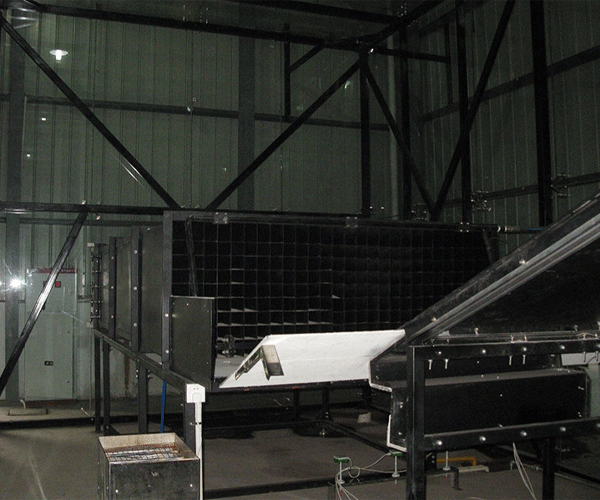
Understanding the purpose of photovoltaic fire testing
A Fire Performance Test Apparatus for Photovoltaic Modules is equipment designed to support a defined test procedure for evaluating the fire-related behavior of photovoltaic modules or relevant module assemblies. Depending on the method, the test may examine how a specimen responds when exposed to an external flame, radiant heat, a burning source, or another prescribed condition.
The exact objective depends on the applicable test standard. For instance, a test may examine flame propagation across a module or roof-mounted assembly, whether burning material or particles fall from the specimen, or how the tested construction behaves during a specified exposure. Other procedures may evaluate a particular electrical or thermal hazard associated with module operation. These are related safety concerns, but they are not the same measurement.
Photovoltaic modules contain several materials assembled into one product. The front glass may behave differently from the polymer encapsulant, rear protective layer, cable insulation, or junction box. The frame and mounting arrangement can also influence how the complete assembly responds to heat or fire. Testing the finished module under a defined procedure can therefore provide information that cannot always be obtained by examining one raw material separately.
For manufacturers, the results may help with product development, design evaluation, quality investigations, and preparation for independent testing. For research institutions, they can provide useful information about the behavior of different module constructions. For testing laboratories, a suitable apparatus can help establish repeatable conditions and collect the information required by the selected procedure.
Why equipment configuration matters
When customers ask us for a photovoltaic module fire testing machine, we first clarify the intended test. Is the project related to an external flame exposure? Does it require a specific roof assembly? Is the laboratory evaluating a complete module or a material used within the module? Is the customer following an international standard, a national code, or an internal research method?
These questions matter because the answers affect the equipment design. A fire exposure test may require a controlled burner or another specified ignition source, a specimen holder, a prescribed mounting angle, and a way to monitor exposure conditions. A different method may require another arrangement entirely. If the customer needs to record temperature, flame progression, specimen condition, or other variables, those requirements must also be considered.
We do not treat every requested feature as a standard function. Instead, we confirm the scope of supply and the technical details before production. This is particularly important for custom equipment because an incorrect assumption at the beginning can lead to avoidable design changes later.
What can the apparatus help evaluate?
Depending on the selected method, a properly configured photovoltaic Fire Performance Testing system may help users evaluate one or more of the following:
The response of a photovoltaic module or assembly to a specified external fire exposure.
Flame spread or other fire-related behavior where the test method defines those observations.
Changes in specimen condition during or after a prescribed exposure.
Temperature or other physical measurements when required by the test procedure.
Comparative performance between module designs or material constructions tested under equivalent conditions.
Recorded test data needed for technical analysis, research, or reporting.
These are potential testing objectives, not a guarantee that every configuration can perform every test. The final functions depend on the apparatus design and the applicable method. We recommend confirming the required observations and acceptance criteria with the responsible testing laboratory or certification organization before ordering the equipment.
2. Working Principle and Main Components of the Testing System
Controlled exposure and specimen support
The basic idea behind fire performance testing is to expose a specimen to a defined condition and observe how it responds. The exposure may come from a specified flame, radiant heat, a burning source, or another method defined by the relevant standard. The test conditions need to be established before the test begins so that the results can be interpreted correctly.
The specimen support system holds the photovoltaic module or test assembly in the position required by the procedure. The support structure must suit the specimen dimensions, weight, orientation, and mounting arrangement. If the method requires a module to be tested as part of a roof construction, the complete assembly and its installation details may be important. A bare module test and a roof-mounted assembly test should not be assumed to produce equivalent results.
During customization, we discuss how the specimen will be loaded, positioned, secured, and removed. We also consider access for inspection and the need to protect the operator from heat, flame, and other test hazards. These details may seem simple, but they have a direct effect on how convenient and repeatable the test process will be.
Fire source and exposure control
The fire source is one of the most important parts of a fire testing apparatus. Its type, position, orientation, output, and exposure duration must be selected according to the test method. Where a standard specifies a burner or a particular exposure condition, substituting another source without technical justification may make the test invalid for its intended purpose.
Depending on the project, the system may need gas supply components, flow control, ignition functions, flame monitoring, or other safety-related features. These functions must be designed around the actual method and the laboratory's operating conditions. They should not be selected simply because they appear on another fire testing machine.
For a customized project, we review the available utilities, the intended operating environment, and the relevant safety requirements. The customer should identify any special requirements for fuel supply, ventilation, exhaust handling, emergency shutdown, and access control. The final design should include the safety measures appropriate to the equipment and test environment.
Measurement and data acquisition
Some fire tests depend mainly on defined exposure conditions and observations of the specimen. Others require measurement devices to record specific variables. Depending on the applicable method, a testing system may incorporate thermocouples, temperature measurement instruments, timing devices, image recording, or other data acquisition functions.
We recommend defining the required output before selecting sensors or software. If the test method requires temperature data at specified locations, the sensor arrangement must be planned accordingly. If the laboratory needs video records or time-based observations, the system should allow those records to be collected and associated with the correct specimen and test conditions.
A computer interface can make data collection more convenient, but software alone cannot ensure that a test is valid. The quality of the result also depends on sensor placement, calibration status where applicable, exposure conditions, specimen preparation, and operator procedure. A good testing system needs to address the complete process.
Typical test workflow
The following table summarizes a general workflow for a fire performance test. It is intended to explain the process rather than replace the instructions in a specific standard.
| Step | Typical operation | Purpose |
|---|
| 1. Confirm test requirements | Identify the applicable standard, specimen type, mounting arrangement, and required observations. | Ensure that the apparatus is configured for the intended test. |
| 2. Prepare the specimen | Record the module identification and prepare the sample according to the test method. | Keep specimen information and preparation conditions traceable. |
| 3. Inspect the equipment | Check the support structure, exposure source, sensors, controls, and safety functions included in the system. | Confirm readiness before starting the test. |
| 4. Set exposure conditions | Establish the required flame, heat exposure, orientation, and duration. | Apply the specified test conditions. |
| 5. Conduct the test | Expose the specimen and observe or record the required variables. | Collect information about the specimen's response. |
| 6. Review the results | Check records, measurements, observations, and any required calculations. | Identify whether the test data are complete and usable. |
| 7. Document the test | Record the specimen details, conditions, observations, and results. | Support traceability and later technical review. |
The precise sequence and acceptance criteria must come from the selected test method. For formal testing, operators should follow the applicable standard and laboratory procedures rather than use this general workflow as a substitute.
Safety and operating environment
Fire testing involves heat, flame, and potentially hazardous combustion products. The test area therefore needs suitable ventilation or exhaust arrangements, safe access, appropriate protective measures, and procedures for dealing with unexpected events. The exact requirements depend on the test method, fuel source, specimen, and laboratory environment.
We encourage customers to discuss these conditions before the design is finalized. The equipment layout should leave sufficient room for loading, inspection, maintenance, and safe operator movement. Where the project requires interlocks, emergency stops, flame monitoring, or other protective functions, these should be defined in the technical specification.
In our view, safe operation is part of equipment usability, not an optional extra. A system that is difficult to access or awkward to maintain can create problems during everyday laboratory work. We therefore consider safety, operating convenience, and the intended test procedure together during the customization process.
3. Key Features and Technical Advantages of a Customized PV Module Fire Testing Apparatus
Designed around the required test method
The most useful feature of a customized Fire Performance Test Apparatus for Photovoltaic Modules is that its configuration can be developed around a defined application. A laboratory that needs to test complete solar modules may have different requirements from a research team studying a building-integrated photovoltaic assembly.
Specimen dimensions, mounting geometry, fire source, exposure conditions, sensors, and data recording needs all affect the design. By confirming these requirements at the beginning, we can identify which functions are necessary and which are not. This helps customers avoid paying for features that do not support their testing objectives.
Customization does not mean that every requirement can be implemented without limits. The final design still needs to be technically feasible, safe, and consistent with the intended method. Any special requirement should be reviewed before it is included in the quotation and production plan.
Flexible specimen handling
Photovoltaic modules are available in different sizes and constructions. Some projects involve standard framed modules, while others may involve glass-glass designs, flexible modules, or building-integrated photovoltaic products. These differences can affect specimen support, access, orientation, and the way the assembly is exposed during testing.
When discussing a customized test apparatus, we ask customers to provide specimen dimensions, approximate weight, mounting details, and any restrictions on handling. Drawings or photographs can be useful when the specimen has an unusual shape or requires a special fixture. The goal is to confirm a practical loading and positioning arrangement before the mechanical structure is manufactured.
Measurement options matched to the project
Not every fire performance test requires the same sensors or recording functions. Some methods may rely on visual observations and specified exposure conditions, while others may require particular temperature measurements or other recorded variables. Adding sensors without understanding the test method can complicate the system without improving the usefulness of the results.
We therefore discuss the measurement requirements with the customer before confirming the configuration. Where data acquisition is needed, the project specification should identify the variables to be recorded, the required measurement locations, the recording procedure, and the expected output format. Specific measurement ranges and accuracy requirements must be confirmed for the selected instruments rather than assumed from a general product description.
Repeatable procedures and clear documentation
Repeatability is an important consideration in laboratory testing. If specimen positioning, exposure conditions, or operating procedures change between tests, the results may become difficult to compare. A well-planned apparatus should make the required setup clear and help operators follow a consistent procedure.
Clear documentation supports this process. Depending on the agreed scope, documentation may include operating instructions, equipment configuration information, electrical diagrams, maintenance guidance, and records of the functional checks performed before delivery. The exact documents supplied should be confirmed in the order agreement.
We also recommend that customers establish a recordkeeping procedure covering specimen identification, test date, operator, exposure settings, environmental conditions where required, and observations. This information can be just as important as the final measurement when the laboratory needs to investigate a result or compare samples over time.
Comparison of common customization areas
| Customization area | Possible design considerations | Information to confirm before ordering |
|---|
| Specimen fixture | Module dimensions, weight, orientation, mounting structure, loading access. | Drawings, sample size, frame details, and intended mounting condition. |
| Fire exposure system | Specified ignition source, burner position, exposure control, safety measures. | Applicable test method and required exposure conditions. |
| Measurement devices | Temperature sensors, timing, visual recording, or other method-specific measurements. | Required variables, measurement positions, and reporting criteria. |
| Control system | Operating sequence, monitoring, alarms, emergency functions, and user interface. | Required automation level and laboratory operating procedures. |
| Data management | Data recording, graph display, export functions, and report structure. | Required file formats, data fields, and traceability needs. |
| Installation and integration | Laboratory space, utilities, ventilation, interfaces, and maintenance access. | Site conditions, existing equipment, and delivery destination. |
This comparison is a project planning guide, not a list of guaranteed standard features. The final equipment configuration and the functions included in the supply must be confirmed in writing.
4. Relevant Standards: How to Choose the Correct Fire Test
IEC 61730-2 and photovoltaic module safety qualification
IEC 61730-2:2023 is titled Photovoltaic (PV) module safety qualification – Part 2: Requirements for testing. According to the International Electrotechnical Commission, it specifies the test sequence used to verify the safety of photovoltaic modules whose construction has been assessed under IEC 61730-1. The tests are intended to identify potential failures of internal and external components that could lead to fire, electric shock, or personal injury.
This standard is an important reference when discussing photovoltaic module safety testing. However, it should not be interpreted as requiring one universal external fire exposure test for every photovoltaic module in every market. The applicable test requirements depend on the standard, the module's intended use, and any additional national or regional rules that apply.
The IEA Photovoltaic Power Systems Programme has also published a report reviewing fire safety laboratories, codes, and standards for building-integrated photovoltaics. The report notes that fire testing requirements for photovoltaic products can depend on the relevant local rules and the intended application. This is one reason why we ask customers to identify the target market and required test method before finalizing the apparatus design.
Official references: IEC 61730-2:2023 and the IEA PVPS report on fire safety of building-integrated photovoltaics.
External fire exposure and roof assembly testing
Some photovoltaic applications involve modules installed as part of a roof or building envelope. In such cases, the performance of the installed assembly may matter, not just the behavior of an individual module. The roof covering, mounting system, supporting construction, installation details, and module arrangement can all influence how a fire exposure test is conducted.
UL 790 is a standard for evaluating the fire performance of roof coverings. It may be relevant when a project involves a roof assembly and the applicable product evaluation calls for that method. However, it should not be treated as a universal photovoltaic module test standard. The required procedure depends on the product, installation arrangement, applicable code, and evaluation programme.
Before specifying an external flame test apparatus for solar panels, customers should confirm whether the required test concerns a standalone module, a roof-mounted photovoltaic system, or a building-integrated photovoltaic assembly. That distinction can affect the specimen arrangement, support structure, exposure source, and the acceptance criteria used to interpret the results.
For reference, see the UL Standards and Engagement standards catalogue and confirm the current edition and scope of the specific standard required for the project.
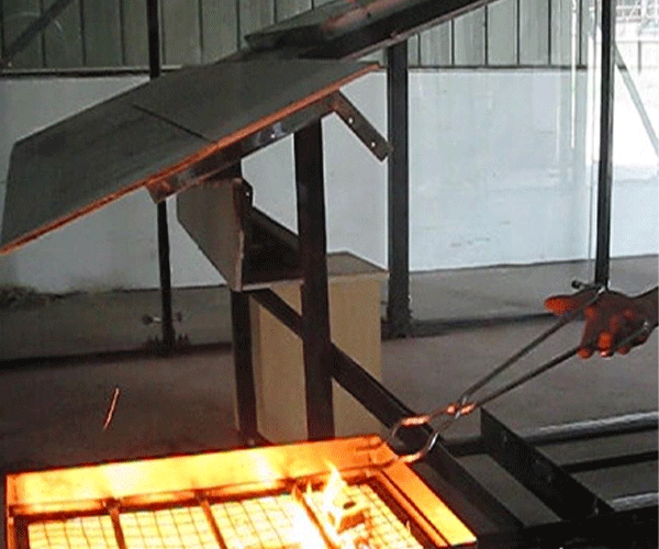
Different fire-related tests answer different questions
A common source of confusion is the assumption that all fire tests measure the same thing. In practice, a flame spread test, an ignitability test, an electrical hot-spot test, and a complete assembly fire exposure test can have different objectives. One examines behavior under an external flame, another examines whether a material ignites under defined conditions, and another evaluates a potential hazard associated with electrical or thermal operation.
The apparatus must therefore be selected according to the question the laboratory is trying to answer. A flame exposure apparatus cannot automatically replace equipment used for electrical safety tests, and a material-level ignitability test does not automatically establish the fire classification of a complete roof assembly.
Standards comparison for equipment planning
| Reference | General purpose | Equipment planning consideration |
|---|
| IEC 61730-2:2023 | Testing requirements for photovoltaic module safety qualification, used with IEC 61730-1. | Identify the applicable test sequence and the specific fire-related requirement relevant to the product. |
| UL 790 | Fire tests for roof coverings. | Confirm whether the project involves a roof covering or installed assembly and whether this method is required. |
| Applicable national or local code | May specify additional fire testing requirements based on product use and installation location. | Confirm the target market, current code, test method, and acceptance criteria with the responsible authority or laboratory. |
Sources: IEC 61730-2:2023, IEC; UL Standards and Engagement catalogue; IEA PVPS fire safety laboratory and standards report. This table is a general guide, not a substitute for the full standards or local regulatory advice.
What to confirm before claiming compliance
When a customer needs equipment for compliance testing, we recommend confirming four items: the exact standard and edition, the specimen or assembly covered by the method, the required apparatus configuration, and the acceptance criteria. If the standard refers to other documents, those references may also need to be reviewed.
It is equally important to distinguish equipment functionality from product certification. Supplying a fire testing apparatus does not automatically certify a photovoltaic module, and a manufacturer's management system certification does not mean that every piece of equipment is independently certified to every test standard. Formal compliance depends on the complete procedure, equipment suitability, test results, and the applicable evaluation process.
5. Application Industries and Practical Value
Photovoltaic module manufacturers
Manufacturers may need fire-related testing during product development, design changes, material selection, or internal quality investigations. A change in encapsulation material, rear protection layer, junction box, frame design, or module construction may affect how the finished product behaves under certain exposure conditions.
A suitable testing system can help a manufacturer investigate these changes under a defined method. When comparing samples, the laboratory should keep the relevant test conditions consistent and document any differences in specimen construction. This makes the results more useful for engineering decisions and reduces the risk of drawing conclusions from tests that were not conducted on a comparable basis.
For manufacturers supplying several markets, it is particularly important to identify which fire test requirements apply to each product and destination. A test programme intended for one application may not cover the requirements of another market or installation type.
Building-integrated photovoltaics
Building-integrated photovoltaics, often called BIPV, combine electricity generation with elements of a building envelope. Depending on the design, photovoltaic products may function as part of a roof, façade, canopy, or another building component. In these applications, fire performance can depend on the complete construction and how the photovoltaic product is installed.
For this reason, the test specimen may need to include more than the photovoltaic module itself. Supporting layers, mounting details, joints, gaps, and the surrounding construction can affect the relevance of the test result. We encourage customers to provide the intended assembly drawings and installation details when requesting a customized apparatus for BIPV testing.
Testing laboratories and inspection organizations
Independent laboratories and quality inspection organizations often need equipment that supports a defined method and produces clear records. They may serve several customers whose specimens differ in size, construction, or intended application. In such cases, the laboratory needs to understand whether the requested tests can be supported by one configuration or whether different apparatus arrangements are necessary.
We can discuss the specimen range, required exposure method, data recording needs, and expected workflow with the laboratory. Where the project involves integration with existing equipment, we also review the available space, utility connections, and interfaces. The purpose is to define the equipment scope clearly before the quotation is finalized.
Research and development institutions
Research teams may use fire performance testing to investigate new module materials, construction techniques, or protective designs. They may also need to compare different configurations to understand how a particular change affects the test outcome.
For research applications, flexible data collection and clear specimen identification can be useful. At the same time, researchers need to distinguish between exploratory experiments and tests performed strictly according to a recognized standard. A customized experimental setup may provide useful research data, but that does not automatically make its results suitable for formal certification.
Related electrical and construction industries
Photovoltaic modules contain electrical and polymeric components that overlap with several other industrial testing fields. Cable insulation, connector materials, protective enclosures, polymer sheets, building panels, and other components may require their own fire-related evaluations.
Our broader testing equipment scope includes construction materials and components, wires and cables, plastics and textiles, electrical plugs, sockets and switches, electronic products, and household appliances. This experience gives us a practical basis for discussing test objectives across different material categories, while recognizing that each product still needs the appropriate test method and equipment configuration.
6. Our Custom Manufacturing Process, Inspection, and Delivery
Step one: understand the customer's application
We begin by asking what the customer wants to test and why. The most useful information includes the photovoltaic module type, specimen dimensions, test standard and edition, required exposure conditions, measurement variables, and the target market. If the customer already has a laboratory setup, drawings, photographs, and interface information can help us understand the project more accurately.
We also ask whether the customer needs a standalone apparatus or a system that integrates with existing equipment. This distinction affects the mechanical structure, control functions, utilities, and project scope. Defining the application clearly at the beginning helps us avoid making assumptions about functions that may not be needed.
Step two: review the technical configuration
After collecting the initial requirements, we review the proposed arrangement against the intended test method. The review may cover the specimen holder, exposure source, sensors, control system, safety functions, data acquisition, and supporting components.
If the project calls for a particular standard, we recommend confirming the relevant edition and any referenced methods before approving the design. When a requirement is unclear, it is better to resolve it during the technical discussion than to discover it after manufacturing has started.
The final technical agreement should identify the main functions, required interfaces, accessories, documentation, acceptance procedure, and any special customer requirements. Specific values for measurement range, accuracy, specimen capacity, and operating conditions should be included only after they have been confirmed for the selected design.
Step three: manufacturing and assembly
The manufacturing process depends on the agreed equipment configuration. It may include preparation of the frame and specimen support, assembly of the exposure system, installation of sensors and controls, wiring, and integration of the data acquisition functions included in the order.
During assembly, we consider the relationship between the mechanical structure and the operating procedure. The specimen needs to be held in the correct position, the exposure source must be arranged according to the agreed design, and measurement devices need to be installed in their intended locations. Electrical components and control functions must also be arranged to support operation and maintenance.
Custom equipment projects can involve non-standard parts or specific interfaces. For that reason, changes to the approved configuration may affect the schedule or require further engineering review. We encourage customers to confirm the principal requirements before production begins so that both sides have a clear understanding of what will be delivered.
Step four: equipment inspection and functional testing
Before shipment, delivery typically includes equipment inspection, functional testing, and preparation of relevant technical documentation. The specific checks depend on the agreed design and acceptance criteria. They may include inspecting the mechanical assembly, checking control functions, reviewing connections, and confirming that the included measurement or recording components operate as intended.
Functional testing should not be confused with formal calibration, independent laboratory validation, or certification to a particular fire test standard. If a customer needs a calibration certificate, third-party report, or documented demonstration against specific standard requirements, that need should be discussed before the order is confirmed. The scope and availability of these services must be agreed rather than assumed.
We also recommend defining acceptance criteria before production. The customer and supplier should know which functions will be checked, what records will be supplied, and how any special requirements will be confirmed. Clear acceptance criteria make the delivery process more straightforward and reduce misunderstandings.
Production lead time and commercial arrangements
The typical production period for our customized testing equipment is approximately 30–60 days, depending on the specifications, degree of customization, component availability, and project complexity. The actual lead time is confirmed after the technical configuration and order requirements have been reviewed.
Payment terms can be negotiated according to the order requirements and the agreed commercial conditions. Before placing an order, customers should confirm the payment schedule, delivery terms, any required documentation, and the responsibilities of each party.
Packaging and transportation
We generally arrange transportation by sea, air, or land, depending on the destination, equipment size, delivery urgency, and agreed shipping plan. Protective packaging helps reduce the risk of damage during handling and transit. Sturdy wooden cases may be used where appropriate, particularly for equipment that needs additional protection during international shipping.
The packing method depends on the equipment structure, fragile components, and shipping requirements. Before shipment, it is useful to confirm the delivery address, consignee information, unloading arrangements, and any destination-specific import or documentation requirements.
For international projects, clear communication about the shipping schedule and receiving conditions can help prevent avoidable delays. We aim to establish these details before dispatch so customers can prepare their laboratory or production site for delivery.
7. Why Choose Guangzhou Chuangge Automation Equipment Co., Ltd.?
A focus on customized testing equipment
At Guangzhou Chuangge Automation Equipment Co., Ltd., we specialize in the customization of testing equipment for industrial and laboratory applications. We understand that different materials and products require different test methods, and we work with customers to clarify the intended application before confirming an equipment configuration.
For a photovoltaic module fire testing project, this means discussing the specimen, required exposure, standard, measurement needs, and operating environment. We do not assume that a generic machine will automatically meet every customer's requirements. Instead, we focus on defining the functions and interfaces needed for the actual project.
Understanding of standards and test procedures
Our work covers several sectors where test procedures and technical requirements are important. We recognize that a standard defines more than the name of a test. It may specify specimen preparation, mounting, exposure conditions, measurement locations, calculations, and reporting requirements.
We therefore encourage customers to provide the exact standard and edition when requesting a quotation. Where the intended application is subject to local regulations or certification requirements, customers should also confirm the applicable rules with the responsible laboratory or authority. This helps us develop the equipment proposal around a clearly defined testing objective.
Certified management systems and technical development
Our company has obtained ISO 9001 quality management system certification, ISO 14001 environmental management system certification, and ISO 45001 occupational health and safety management system certification. These management systems reflect our commitment to organized quality processes, environmental management, and workplace health and safety.
According to our company information, our intellectual property portfolio contains more than 20 patents, including invention patents, utility model patents, and software patents. These patents form part of our technical development work. The applicability of any particular patent to a specific photovoltaic fire testing configuration should be confirmed rather than assumed.
Clear communication throughout the project
Customized equipment requires communication between the customer and the engineering team. We aim to clarify the technical scope, production schedule, inspection arrangements, packaging, and delivery requirements before the order is finalized.
Customers can help move the process forward by sharing the target test standard, specimen drawings, expected measurements, laboratory conditions, and any existing equipment interfaces. If a requirement is still under review, we can discuss the options and identify which details need to be resolved before the design is approved.
If you are looking for a Fire Performance Test Apparatus for Photovoltaic Modules, we welcome you to contact Guangzhou Chuangge Automation Equipment Co., Ltd. with your project details. We can discuss the intended test procedure, technical configuration, customization requirements, and delivery plan before preparing a suitable proposal.
8. Frequently Asked Questions About Photovoltaic Module Fire Testing Equipment
Q1. What is a Fire Performance Test Apparatus for Photovoltaic Modules used for?
It is used to support a defined fire-related test procedure for photovoltaic modules or relevant assemblies. Depending on the method, it may help evaluate the response to an external fire exposure, record specified measurements, and document observations. The exact function depends on the apparatus configuration and applicable test standard.
Q2. Can one apparatus perform every photovoltaic fire test?
Not necessarily. Different methods may use different fire sources, specimen arrangements, exposure conditions, measurements, and acceptance criteria. A system designed for one procedure may need substantial changes or additional equipment to support another. We recommend identifying the required methods before selecting the configuration.
Q3. Is IEC 61730-2 the same as a roof covering fire test?
No. IEC 61730-2 is part of the photovoltaic module safety qualification framework and must be used with IEC 61730-1. A roof covering fire test, such as one performed under an applicable UL 790 procedure, has its own scope and requirements. The correct method depends on the product, installation arrangement, and applicable rules.
Q4. Can the apparatus be customized for different module sizes?
Customization can be discussed based on specimen dimensions, weight, mounting arrangement, and the requirements of the selected test method. Customers should provide drawings or measurements so that the support structure and handling arrangement can be reviewed. The available specimen range must be confirmed in the final technical specification.
Q5. Can temperature and other data be recorded automatically?
Data acquisition functions can be considered when they are required by the test procedure or customer workflow. The type and number of sensors, measurement locations, recording functions, and software outputs depend on the agreed configuration. We recommend identifying the required variables before finalizing the design.
Q6. Does purchasing the apparatus mean our photovoltaic modules are certified?
No. Purchasing testing equipment does not automatically certify a photovoltaic module or establish that it complies with a particular standard. Compliance depends on the applicable requirements, the suitability of the complete test setup, the test procedure, the results, and the relevant certification or evaluation process.
Q7. What information should I provide when requesting a quotation?
Please provide the module type, specimen dimensions, target standard and edition, required fire exposure, measurement needs, intended application, laboratory conditions, and destination country. If you have drawings, photographs, or details of existing equipment, these can help us understand the project and review the proposed configuration more efficiently.
Q8. How long does production take?
The typical production period is approximately 30–60 days, depending on the final specifications, customization requirements, and component availability. We confirm the actual schedule after reviewing the technical configuration and order details.
Q9. What is included in the delivery?
Delivery typically includes equipment inspection, functional testing, and relevant technical documentation according to the agreed scope. Special calibration certificates, third-party reports, installation services, or additional accessories should be discussed and confirmed in the contract if they are required.
Q10. How is the equipment shipped?
Shipping may be arranged by sea, air, or land, depending on the destination, shipment size, urgency, and agreed logistics plan. Protective materials and sturdy wooden cases may be used as appropriate to help protect the equipment during transportation.
Conclusion: Build the Right Fire Testing Solution for Your Photovoltaic Modules
Fire safety is an important part of photovoltaic product development, but the correct testing approach depends on the product and its intended use. A Fire Performance Test Apparatus for Photovoltaic Modules needs to match the applicable test method, specimen arrangement, exposure conditions, measurement requirements, and laboratory operating environment.
Standards such as IEC 61730-2 provide a framework for photovoltaic module safety qualification, while external fire exposure requirements may also depend on roof construction, building-integrated applications, and local regulations. These methods should not be treated as interchangeable. Confirming the exact standard and edition before equipment design begins is one of the most practical ways to avoid unnecessary changes and improve project planning.
At Guangzhou Chuangge Automation Equipment Co., Ltd., we focus on customized testing equipment and work with customers to define a configuration suited to their testing objectives. Our project process can include technical requirement review, equipment manufacturing, functional inspection, documentation preparation, protective packaging, and transportation arrangements. Production typically takes 30–60 days, depending on the agreed specifications and customization needs.
If you are planning a photovoltaic module fire testing project, developing a building-integrated solar product, or equipping a laboratory for fire-related evaluation, contact us with your test requirements. We will work with you to review the application, clarify the necessary functions, and discuss a practical equipment solution for your project.


