Dynamic Response Test Apparatus for Glass Bulbs Used in Automatic Fire Extinguishing Systems
1. Introduction: Why Dynamic Response Testing Matters for Fire Protection Glass Bulbs
In an automatic fire extinguishing system, a small glass bulb can play a very important role. It may look like a simple glass component, but its response to heat can influence when a sprinkler or another compatible fire protection device activates. If the bulb responds too slowly, the system may not operate at the intended time. If its thermal response characteristics are inconsistent, the performance of the finished product may also become less predictable. That is why manufacturers need reliable ways to evaluate glass bulb response performance during product development and quality control.
At Guangzhou Chuangge Automation Equipment Co., Ltd., we specialize in customized testing equipment for industrial manufacturers and laboratories. We understand that fire protection products cannot be evaluated by appearance alone. Their performance needs to be checked using suitable test methods, controlled conditions, and clearly defined acceptance criteria. Our Dynamic Response Test Apparatus for Glass Bulbs Used in Automatic Fire Extinguishing Systems is designed around this practical testing need: helping customers evaluate the dynamic thermal response of temperature-sensitive glass bulbs under specified test conditions.
A glass bulb used in a fire sprinkler typically contains a temperature-sensitive liquid. As the surrounding temperature rises, the liquid expands and the pressure inside the bulb changes. When the relevant operating conditions are reached, the bulb breaks and allows the associated sprinkler mechanism to operate. However, the temperature at which a bulb eventually breaks is only one part of its performance. The speed at which it responds to a changing hot-air environment is another important consideration.
This distinction is the reason dynamic response testing matters. A static operating temperature test focuses on the temperature at which a glass bulb breaks under a defined heating procedure. A dynamic response test examines how the bulb behaves when exposed to heated airflow under specified conditions. The two tests provide different types of information, so one should not automatically be treated as a substitute for the other.
For manufacturers developing fast-response, special-response, or standard-response glass bulbs, this type of test can support product evaluation, process improvement, and batch quality management. It can also help engineering teams investigate whether changes in bulb dimensions, working fluid, manufacturing processes, or related design factors are associated with changes in thermal response.
We develop testing equipment with the actual testing task in mind. Instead of assuming that every customer needs exactly the same configuration, we discuss the specimen type, applicable standard, required test procedure, measurement needs, and laboratory operating conditions before confirming a technical proposal. This approach is especially important for specialized Fire Protection Testing Equipment, where a small difference in the test setup can affect how results should be interpreted.
Our company works across several industrial testing fields, including building materials, wires and cables, plastics, textiles, electrical accessories, electronic products, and fire protection equipment. We provide customized equipment solutions based on agreed requirements, with a typical production cycle of 30 to 60 days depending on the project. Before delivery, we carry out functional inspection and performance verification according to the agreed scope, and we provide technical documentation as specified in the order.
When customers search for a Dynamic Response Test Apparatus for Glass Bulbs Used in Automatic Fire Extinguishing Systems, they are usually looking for more than a machine name. They need to know what the equipment evaluates, which test method it supports, how results can be used, and what information is required before purchasing. We will explain these points in practical language throughout this page.
2. Working Principle: How a Dynamic Response Test Is Evaluated
2.1 Understanding the thermal response of a glass bulb
A temperature-sensitive glass bulb is designed to respond to heat in a controlled way. In a typical sprinkler application, the bulb forms part of a heat-responsive assembly. When the surrounding temperature increases, heat transfers from the air to the bulb and then into its internal contents. The bulb's physical properties, dimensions, thermal characteristics, and exposure conditions all influence how quickly its temperature changes.
It is useful to picture the process as a small object being placed in a stream of hot air. The air may reach a certain temperature almost immediately, but the glass bulb itself does not necessarily reach that temperature at the same moment. Heat needs time to move from the air through the glass and into the bulb's contents. The bulb's response therefore depends on both the surrounding conditions and its own thermal behavior.
Dynamic response testing evaluates this time-dependent behavior using a defined test arrangement. Depending on the applicable procedure, the apparatus may control or monitor factors such as air temperature, air velocity, specimen position, exposure conditions, and measurement timing. The exact arrangement must be selected according to the relevant standard or agreed test method rather than assumed to be universal.
For suitable glass bulb testing methods, a key result is the Response Time Index, commonly abbreviated as RTI. RTI is a measure associated with the thermal sensitivity of a heat-responsive element under specified test conditions. It is not simply the operating temperature printed on a product label, and it should not be interpreted as a direct measurement of the time required for a sprinkler to control a real fire.
2.2 What is the Response Time Index?
RTI helps engineers compare the thermal response characteristics of compatible heat-responsive elements when the required test conditions and calculation methods are used. In general terms, a lower RTI indicates a more thermally responsive element under the applicable test framework. However, comparisons are meaningful only when the tested products, procedures, and result calculations are sufficiently comparable.
One simplified form of the relationship used in thermal response analysis is:
RTI = τ × √u
In this expression, τ represents the thermal response time constant, while u represents the relevant gas velocity under the applicable test method. RTI is commonly expressed in units of (m·s)0.5. This formula is provided here to explain the basic relationship, not as a complete testing procedure. The precise definitions, measurement steps, assumptions, and calculation requirements must follow the standard applicable to the specific product.
Why does air velocity matter? A bulb exposed to moving hot air may receive heat at a different rate from a bulb exposed to slower-moving air. If the airflow is not properly controlled or measured, the test may produce results that cannot be compared fairly. This is one reason a dynamic response test apparatus needs a carefully designed airflow arrangement and a clear operating procedure.
At Chuangge, we recommend that customers identify the target standard and test scope before deciding on equipment configuration. A machine intended for a particular glass bulb test should not be assumed to support every sprinkler test, every heat-responsive component, or every possible response classification without reviewing the relevant requirements.
2.3 A typical testing workflow
The actual sequence depends on the standard and equipment configuration, but a typical project may involve the following stages:
| Stage | Typical activity | Purpose |
|---|
| 1. Test planning | Confirm specimen type, applicable standard, test conditions, and acceptance criteria. | Ensure the test arrangement matches the intended evaluation. |
| 2. Specimen preparation | Identify, inspect, and prepare the glass bulb samples according to the selected method. | Reduce avoidable differences caused by sample handling or identification errors. |
| 3. Equipment setup | Configure the airflow, heating arrangement, specimen fixture, and measuring devices as required. | Establish the conditions needed for the specified procedure. |
| 4. Test exposure | Expose the specimen to the prescribed thermal and airflow conditions. | Observe the time-dependent thermal response. |
| 5. Data recording | Record relevant measurements and test events. | Provide information for analysis and calculation. |
| 6. Result evaluation | Calculate or review response results using the applicable method. | Compare the findings with the agreed requirements. |
Source note: This workflow is a general explanation of a laboratory testing process, not a verbatim procedure from a standard. For requirements relating to sprinkler response testing, refer to ISO 6182-1:2021, particularly its provisions on sensitivity testing and RTI. Official reference: ISO 6182-1:2021, Fire protection — Automatic sprinkler systems — Part 1: Requirements and test methods for sprinklers.
2.4 Why test conditions must be controlled
A test result is only useful when the conditions behind it are understood. Consider a situation in which two laboratories test similar glass bulbs but use different airflow conditions, different specimen positions, or different data processing methods. Even if both laboratories operate their equipment correctly, the resulting figures may not be directly comparable.
For this reason, test planning should cover more than the maximum temperature of the heating system. Airflow stability, temperature measurement, specimen mounting, sensor placement, measurement timing, and the handling of test samples may all matter. The importance of each parameter depends on the specific test method.
Our engineering approach is to confirm these requirements before finalizing the design. If a customer already has a laboratory procedure, we can use the supplied documentation as the basis for technical discussions. If the customer is developing a new test setup, we first need to clarify the intended evaluation and identify the relevant standard or method. We do not assume that a general-purpose heating device can automatically meet the requirements of a dynamic response test.
3. Main Features and Technical Considerations
3.1 A configuration based on the intended test method
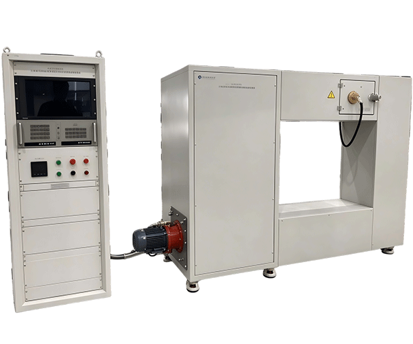
The main purpose of the Dynamic Response Test Apparatus for Glass Bulbs Used in Automatic Fire Extinguishing Systems is to provide a controlled setup for evaluating the thermal response of suitable glass bulb specimens. The final configuration depends on the required test method, specimen design, measurement range, and laboratory workflow.
For one customer, the priority may be a repeatable arrangement for routine product development. Another customer may need a more specialized configuration for research, comparative testing, or internal quality checks. These are different requirements, and we believe the equipment proposal should reflect that difference instead of offering the same specification to every buyer.
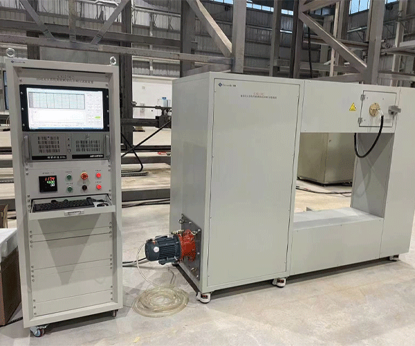
Depending on the agreed design, the apparatus may incorporate a heating and airflow system, specimen fixtures, temperature measurement components, airflow measurement or control devices, a data acquisition arrangement, and operating controls. These are possible configuration elements, not a declaration that every unit automatically includes every item. The confirmed quotation and technical specification should identify the actual components supplied.
3.2 Airflow and temperature management
Dynamic response testing depends on the conditions surrounding the specimen. The equipment therefore needs a suitable way to establish and monitor the thermal environment required by the selected procedure. Heating capacity alone is not enough. The way heat and air move around the test specimen can also influence the measurement.
During equipment planning, we review the requested temperature conditions, airflow requirements, specimen dimensions, and relevant measurement devices. We also discuss the laboratory's available utilities and installation space where these factors affect the design. The goal is to build a test arrangement that is suitable for the agreed procedure and practical for the people who will operate it.
Customers should also consider how operating conditions will be checked during routine use. A displayed value is useful only when the associated sensor, measurement range, installation, and maintenance requirements are appropriate. If formal calibration or traceability is required, this should be specified separately and confirmed with the relevant service provider or laboratory. Functional inspection before shipment should not be confused with formal calibration.
3.3 Specimen positioning and repeatability
A glass bulb is a relatively small specimen, which makes consistent positioning important. If the bulb is placed differently from one test to another, its exposure to the surrounding airflow may change. A suitable fixture helps establish the intended position and reduces avoidable differences caused by manual handling.
Fixture design should take the actual specimen geometry and test method into account. The support must hold the sample in the required position without introducing an unintended influence on the thermal exposure. At the same time, the operator needs a practical way to load and remove samples while following the applicable safety procedure.
Repeatability also depends on factors outside the fixture itself. Sample condition, room environment, test preparation, instrument status, and operator practice can all influence the quality of the results. Good equipment supports a consistent method, but it cannot remove the need for proper sample handling and documented operating procedures.
3.4 Data recording and result review
For product development and quality management, it is often important to keep more than a final RTI figure. Depending on the selected method, useful records may include specimen identification, test conditions, measured temperatures, airflow information, relevant timing data, calculations, and observations made during the test.
A suitable data recording arrangement can help engineers compare samples and investigate changes between production batches. It can also make internal reviews more straightforward when a result appears unusual. Before confirming the equipment design, we discuss which data must be displayed, recorded, exported, or included in the customer's report.
We avoid assuming that every customer needs the same software or reporting format. Some laboratories may prefer a simple operating interface and manual report preparation. Others may require more structured data management. These details should be agreed during technical clarification so that the supplied equipment meets the real workflow rather than adding features that are not needed.
3.5 Operator usability and maintenance
Specialized test equipment should be technically suitable without becoming unnecessarily difficult to operate. Clear controls, accessible fixtures, readable measurements, and a practical setup procedure can help reduce mistakes during routine testing. We therefore consider operator workflow as part of the customization process.
Maintenance should also be discussed before delivery. Heating elements, sensors, airflow components, fixtures, electrical connections, and moving parts, where fitted, may require periodic inspection. The exact maintenance schedule depends on the supplied design and operating conditions, so it should be based on the equipment documentation rather than a generic interval applied to every machine.
For laboratories that test glass bulbs regularly, we recommend establishing written procedures for startup, stabilization, specimen installation, data recording, shutdown, and routine checks. These procedures help different operators follow the same approach and make test records easier to review later.
3.6 Summary of key design considerations
| Design area | What we clarify with the customer | Why it matters |
|---|
| Thermal environment | Required temperature conditions and heating arrangement. | The specimen must be exposed according to the selected test method. |
| Airflow | Required gas velocity, airflow stability, and measurement approach. | Airflow affects heat transfer and the interpretation of dynamic response. |
| Specimen fixture | Bulb dimensions, mounting position, and sample handling requirements. | Consistent positioning helps reduce avoidable test variation. |
| Measurement | Required sensors, measurement ranges, recording frequency, and data format. | The equipment must capture the information required by the test method. |
| Control and safety | Operating interface, electrical supply, protective measures, and shutdown procedure. | Supports practical operation and appropriate risk management. |
| Documentation | Operating instructions, technical specifications, inspection records, and agreed reports. | Helps the laboratory operate and maintain the equipment consistently. |
Source note: The table above summarizes engineering discussion points for customized test equipment; it is not a list of mandatory requirements taken directly from a single standard. Applicable requirements must be verified against the selected test method and the confirmed technical specification.
4. Standards, RTI Classification, and Correct Interpretation of Results
4.1 GB 18428 and glass bulbs used in automatic fire extinguishing systems
When the product being evaluated is a temperature-sensitive glass bulb used in an automatic fire extinguishing system, GB 18428 is an important reference to review for projects targeting the relevant Chinese standard. The standard is titled Glass bulbs used for automatic fire extinguishing systems and addresses glass bulbs intended for these applications. Its scope and current applicability should be checked against the customer's product and compliance requirements before the test system is specified.
The publicly available standard information describes static operating temperature, Response Time Index, and dynamic response performance among the relevant concepts. It also describes different response classifications for glass bulbs. These classifications are based on defined test requirements and should not be assigned merely by looking at the nominal operating temperature or the color of the bulb's working fluid.
For procurement projects, we recommend that customers confirm the applicable edition, any amendments, the required specimen type, and the precise clauses relevant to their intended test. A standard may be revised, and a project may also be governed by additional market-specific requirements. Confirming the correct edition at the beginning can prevent avoidable changes later in the equipment design process.
Reference: GB 18428-2010 — Glass bulbs used for automatic fire extinguishing systems. This link provides publicly available standard information. Buyers should verify the official current status and any applicable revisions through the relevant standards authority before using it as a compliance basis.
4.2 ISO 6182-1:2021 and sprinkler testing
ISO 6182-1:2021 is titled Fire protection — Automatic sprinkler systems — Part 1: Requirements and test methods for sprinklers. It covers performance and marking requirements and test methods for several sprinkler types used in water-based fire protection systems. The document includes provisions addressing sensitivity testing and Response Time Index for applicable sprinkler configurations.
This standard is relevant when the glass bulb is being evaluated as part of a sprinkler product or when the testing project is tied to sprinkler performance requirements. However, it is important to distinguish the scope of a glass bulb test from the scope of a complete sprinkler test. A sprinkler assembly includes other components and performance characteristics, so a test apparatus designed for glass bulb dynamic response should not automatically be described as a complete sprinkler testing system.
Our recommendation is simple: start with the product and the clause that must be evaluated, then select the equipment configuration. This avoids the common mistake of purchasing a machine based only on a general product name without confirming whether it supports the actual test procedure.
Official reference: ISO 6182-1:2021 — International Organization for Standardization.
4.3 Understanding response classifications
Response classifications are meaningful only within the relevant standard and test procedure. For example, the publicly available information for GB 18428-2010 describes fast-response, special-response, and standard-response glass bulb categories using RTI-related criteria. The figures below summarize those published criteria for explanatory purposes. They should not be treated as universal limits for every market or every type of thermal element.
| Glass bulb response category | RTI criteria described in GB 18428-2010 | Practical interpretation |
|---|
| Fast response | RTI less than or equal to 50 (m·s)0.5 | Represents a lower RTI range under the standard's defined test method. |
| Special response | Average RTI from 50 to 80 (m·s)0.5, with individual values subject to the stated limits. | Evaluation involves both the average and the permitted range of individual results. |
| Standard response | RTI greater than 80 and less than or equal to 350 (m·s)0.5 | Represents the standard-response range specified in that edition. |
Source: GB 18428-2010, publicly available standard information, Glass bulbs used for automatic fire extinguishing systems. The figures are reproduced as a summary of the cited edition, not as a statement that the same classification limits apply to all jurisdictions or later editions.
When reviewing results, laboratories should check the required number of specimens, the treatment of individual values, any average-value criteria, and the acceptance rules specified by the applicable method. A single result may be useful for development work, but it may not be sufficient to establish that a product meets all applicable requirements.
4.4 Static operating temperature is not the same as dynamic response
One of the most important distinctions in glass bulb testing is the difference between operating temperature and thermal response. Operating temperature describes the temperature associated with activation under the defined test procedure. Dynamic response concerns how the element responds over time when exposed to specified thermal conditions.
Two bulbs may have the same nominal operating temperature but different thermal response characteristics. Conversely, a low RTI result does not by itself tell an engineer whether the bulb has passed every other test required for its intended application. The product may also be subject to requirements concerning strength, integrity, environmental exposure, compatibility, or the performance of the complete sprinkler assembly.
For that reason, we encourage customers to keep separate records for different test purposes. A static temperature result should be labelled as such. A dynamic response result should include the applicable test method and relevant conditions. Clear labels make it easier to compare data correctly and reduce confusion between departments, laboratories, and suppliers.
4.5 A testing apparatus does not automatically certify the product
We want to be clear about this point because it matters in fire protection work. Purchasing a Dynamic Response Test Apparatus for Glass Bulbs Used in Automatic Fire Extinguishing Systems does not automatically mean that the glass bulbs, sprinkler assemblies, or finished fire extinguishing systems are certified. The equipment is a tool used to carry out the agreed evaluation.
Formal product certification may involve additional test methods, sample quantities, independent assessment, quality system review, documentation, and other requirements defined by the applicable certification scheme. The responsibilities of the equipment supplier, product manufacturer, testing laboratory, and certification body are different.
Our role is to work with the customer to define a suitable equipment configuration, provide the agreed technical documentation, and verify the supplied machine's functions within the confirmed scope. Where the customer needs accredited testing, traceable calibration, or certification services, those requirements should be arranged with appropriately qualified organizations and stated clearly in the project plan.
5. Applications: Who Can Benefit from Dynamic Response Testing?
5.1 Glass bulb manufacturers
Glass bulb manufacturers are a direct application group for this type of test apparatus. During product development, engineers may need to evaluate how a change in glass geometry, working fluid, material selection, or manufacturing conditions affects thermal response. Dynamic testing provides a way to examine these effects under controlled conditions.
During routine production, the same type of testing can support internal quality monitoring. For example, if results begin to shift between production batches, engineers can review the recorded conditions and investigate possible causes. The test does not identify every root cause automatically, but it provides data that can help narrow the investigation.
For manufacturers supplying different operating temperature ratings or response classes, a clearly defined test procedure is especially useful. It helps teams keep sample identification, test conditions, and acceptance criteria organized rather than relying on informal comparisons.
5.2 Automatic sprinkler manufacturers
Sprinkler manufacturers may need to evaluate glass bulbs used in their sprinkler assemblies, particularly when reviewing supplier samples, developing new product designs, or conducting internal verification. The bulb's thermal behavior is one part of the overall sprinkler design, so test results need to be interpreted alongside the other requirements applicable to the finished product.
A dynamic response test apparatus can support development and quality control when the selected setup matches the relevant test method. If the project requires evaluation of complete sprinkler assemblies, the customer should identify any additional equipment needed for those tests. A glass bulb test setup should not be assumed to replace pressure, leakage, water distribution, or other sprinkler performance tests.
5.3 Fire protection equipment research and development
Research teams often need repeatable data to compare design alternatives. A controlled test arrangement can help them examine whether changes in a specimen's structure or production process are associated with different response results. It can also support early-stage investigation before a product moves into broader validation.
For research applications, the ability to record test conditions is especially valuable. If engineers want to compare several design versions, they need to know whether the specimens were exposed under comparable conditions. The test report should therefore include enough information to explain how the result was obtained and what limitations apply.
5.4 Independent laboratories and quality inspection organizations
Laboratories and quality inspection organizations may use dynamic response testing as part of a broader evaluation program. Their needs can differ from those of a production line. A laboratory may place more emphasis on method documentation, traceable measurement devices, sample identification, data retention, and the ability to review previous test records.
Before purchasing, laboratories should define whether the apparatus is intended for internal research, routine quality control, contract testing, or a formal conformity assessment program. The intended use affects the requirements for documentation, calibration, maintenance, uncertainty evaluation, and any accreditation-related obligations.
We can discuss these needs during project clarification, but the laboratory remains responsible for confirming its regulatory and accreditation requirements. Equipment design should support the intended work without implying that accreditation or approval is automatically obtained through the purchase.
5.5 Fire protection product supply chains
Component suppliers, sprinkler manufacturers, and finished-product manufacturers often work together across different locations. A consistent test procedure can help these organizations discuss performance using a shared set of definitions and records. When a supplier's results differ from those of a customer laboratory, the first step is to compare the methods, conditions, instruments, and sample preparation before assuming that one result is incorrect.
A suitable dynamic response test apparatus can therefore be part of a wider quality management process. It supports evidence-based communication between engineering, production, purchasing, and quality teams. Its value is not simply that it produces a number; it helps people understand how that number was obtained.
5.6 Comparing application needs
| Application group | Typical testing objective | Points to confirm before purchasing |
|---|
| Glass bulb manufacturer | Product development and production consistency. | Bulb design, response category, specimen quantity, and routine test frequency. |
| Sprinkler manufacturer | Evaluate glass bulbs used in sprinkler assemblies. | Whether the test covers bulbs only or forms part of a broader sprinkler test program. |
| Research and development team | Compare design changes and investigate thermal response. | Measurement data, recording format, test repeatability, and experimental scope. |
| Testing laboratory | Conduct documented testing against an identified method. | Applicable standard, calibration requirements, traceability, reporting, and accreditation scope. |
| Quality inspection department | Monitor samples and investigate differences between batches. | Sampling plan, acceptance criteria, specimen identification, and record retention. |
Source note: This table summarizes common engineering and purchasing considerations rather than reporting survey data. The actual scope for each organization should be confirmed from its product specifications, applicable standards, and quality procedures.
6. How We Customize, Manufacture, Inspect, and Deliver the Equipment
6.1 We begin with the test requirement, not just the product name
At Guangzhou Chuangge Automation Equipment Co., Ltd., our first step is to understand what the customer needs to measure. The product name gives us a starting point, but it does not tell us every technical detail. Two customers asking for a dynamic response test apparatus may have different specimen designs, test standards, laboratory conditions, and data requirements.
During the initial discussion, we normally clarify the following information:
The type and intended application of the glass bulb.
The applicable standard, edition, and specific test clause, if already identified.
Specimen dimensions and the required mounting arrangement.
Required temperature and airflow conditions.
Measurement range, recording needs, and preferred data format.
Laboratory power supply, installation space, and operating environment.
Any special requirements for safety, documentation, calibration, or external verification.
Customers do not need to have every answer ready before contacting us. If the test requirement is still being developed, we can discuss the available information and identify which technical points need confirmation. However, the final design and quotation should be based on a clear, agreed specification rather than assumptions about unconfirmed capabilities.
6.2 Engineering design and component selection
Once the scope is clear, the engineering stage focuses on the relationship between the test method and the equipment structure. This may involve the heating arrangement, airflow components, specimen fixtures, measurement devices, control system, protective measures, and data recording functions.
Component selection should be appropriate for the required operating conditions and the intended use. Sensors need suitable measurement ranges. Fixtures must suit the sample geometry. The control system must support the specified procedure. If the customer has a particular requirement for a data interface or report format, it should be reviewed before manufacturing begins.
We also discuss what is not included. For example, a customer may require a test machine, calibration services, installation support, training, or an independent verification report. These are separate project items and should be listed clearly in the quotation or technical agreement. Clear boundaries help avoid misunderstandings at delivery.
6.3 Manufacturing and assembly
After the design and commercial details are confirmed, the project moves into manufacturing and assembly. The exact process depends on the equipment configuration, but it may include structural fabrication, component preparation, electrical assembly, installation of measurement devices, control integration, and mechanical adjustment.
For customized equipment, assembly is not just a matter of putting parts together. The components need to work as a coordinated system. The heating arrangement, airflow path, specimen holder, measurement points, and control functions must be consistent with the agreed design. If the customer has provided a particular test procedure, the assembly should be reviewed against that requirement before the machine is released.
We keep technical communication open during the project because late changes to specimen dimensions, measurement needs, or test conditions can affect the equipment design and production schedule. Confirming these details early is usually more efficient than making major changes after assembly has begun.
6.4 Functional inspection and performance verification before shipment
Before delivery, we carry out functional inspection and performance verification within the agreed scope. This helps confirm that the supplied equipment's specified functions operate as intended and that the relevant checks have been completed before shipment.
The actual inspection items depend on the design and contract. They may include checking control functions, heating operation, measurement displays, airflow-related functions, specimen fixtures, electrical connections, and other agreed features. Where appropriate, the project documentation can record the checks performed and their results.
It is important to distinguish these checks from formal calibration or independent certification. Functional verification demonstrates that the equipment has been checked within a defined scope; it does not automatically establish measurement traceability, laboratory accreditation, or compliance with every clause of a product standard. If the customer requires a formal calibration certificate or independent assessment, that requirement should be agreed before the order is finalized.
6.5 Production lead time and delivery planning
For our customized fire protection testing equipment, the typical production cycle is approximately 30 to 60 days. The actual lead time depends on the equipment specification, level of customization, component availability, design confirmation, and project workload. A relatively straightforward configuration may follow a different schedule from a system requiring specialized measurement functions or additional integration.
We recommend confirming the delivery schedule after the technical scope has been reviewed. If the customer has a fixed laboratory installation date, product development milestone, or inspection schedule, that information should be shared at the quotation stage. It helps us assess the production plan and identify any constraints early.
Payment terms are negotiable and should be stated in the commercial agreement. Depending on the destination and the customer's logistics requirements, shipment can be arranged by sea, air, or land. The appropriate method depends on delivery urgency, destination, package size, handling requirements, and total logistics cost.
6.6 Packaging and technical documentation
Testing equipment may contain precision components, electrical parts, sensors, and other items that need protection during transport. We select protective packaging according to the equipment structure and shipping arrangement. Sturdy wooden cases may be used where appropriate to help protect the equipment against impact and handling during transportation.
Technical documents are provided as agreed in the order. Depending on the project, these may include an equipment specification, operating instructions, maintenance information, inspection records, electrical information, or other documents relevant to the supplied configuration. Customers should identify any special language, document format, or reporting requirements before delivery so that the scope can be confirmed in advance.
Our aim is to supply equipment that customers can understand, install, and operate according to the agreed instructions. For a specialized testing machine, clear documentation is part of the practical value of the delivery because it helps operators use the equipment consistently and supports future maintenance.
7. Why Work with Guangzhou Chuangge Automation Equipment Co., Ltd.?
7.1 Experience across different industrial testing applications
Our work focuses on customized testing equipment for manufacturers and laboratories. We serve application areas that include construction materials and components, wires and cables, plastics and textiles, plugs, sockets and switches, electronic products, home appliances, and fire protection products.
These industries do not all test products in the same way. Some require mechanical measurements, while others focus on electrical performance, environmental behavior, combustion characteristics, or thermal response. Working across different application areas gives our team a practical basis for discussing test objectives, equipment structure, and the importance of matching a machine to its intended procedure.
For the Dynamic Response Test Apparatus for Glass Bulbs Used in Automatic Fire Extinguishing Systems, this means we focus on the actual thermal response evaluation and the customer's operating requirements. We do not assume that a generic heating system is automatically suitable for the test simply because it can produce hot air.
7.2 Customization for real laboratory needs
Not every laboratory has the same floor space, specimen dimensions, measurement requirements, or reporting workflow. A customized solution can help address these differences when they are clearly defined during the engineering stage.
We discuss the target test method first and then review the features required to support it. Depending on the agreed scope, this may involve specimen fixtures, heating and airflow arrangements, measurement components, controls, and data recording. We aim to avoid unnecessary complexity while ensuring that important requirements are not overlooked.
Customization does not mean that any requested configuration can be guaranteed without technical review. If a requirement conflicts with the test method, exceeds the proposed design, or needs an external service, we discuss that issue before confirming the final specification. This is a more reliable way to plan a project than promising features before checking what they require.
7.3 Quality management and documented processes
Our company operates under a quality-oriented business philosophy: ensuring survival through high technology and driving development through high quality. We have obtained ISO 9001 quality management system certification, ISO 14001 environmental management system certification, and ISO 45001 occupational health and safety management system certification.
These management system certifications relate to the respective management systems. They should not be confused with automatic certification of every individual machine or proof that a particular test apparatus meets every requirement of a particular product standard. Equipment-specific acceptance and verification remain tied to the technical specification, inspection scope, and applicable test method.
We also have a portfolio of more than 20 patents, including invention patents, utility model patents, and software patents. This intellectual property background forms part of our broader work in equipment development. For any specific project, customers should evaluate the confirmed configuration and documented functions rather than assume that a patent portfolio alone establishes a particular performance result.
7.4 Technical communication from inquiry to delivery
A specialized test equipment project usually involves several people: the purchasing team, the laboratory operator, the quality manager, and the engineer responsible for the test method. If each person has a different understanding of the required machine, the project can become complicated very quickly.
We therefore encourage customers to share the test standard, specimen information, and intended use as early as possible. These details help us prepare a more relevant proposal and reduce uncertainty around the configuration, schedule, documentation, and delivery requirements.
When the specification is confirmed, both sides have a clearer basis for reviewing manufacturing progress and acceptance. If the requirement changes, the effect on the design, price, and delivery time should be discussed rather than left unclear. We believe this straightforward approach is important for long-term cooperation.
7.5 A practical approach to purchasing
Choosing a testing apparatus is not just a comparison of purchase prices. Buyers should also consider whether the equipment supports the required method, whether the measurement functions are suitable, what documentation is included, how maintenance will be handled, and whether future changes in the test requirement could affect the configuration.
We encourage customers to compare quotations using the same technical scope. A lower-priced offer may exclude measurement devices, data recording, documentation, or verification activities that another proposal includes. On the other hand, an elaborate configuration may not be necessary for a laboratory with a clearly limited testing objective.
Our role is to clarify the proposed scope and provide a solution based on the agreed needs. The final purchasing decision should be supported by a clear specification, a realistic delivery schedule, and a shared understanding of what will be inspected before shipment.
8. Frequently Asked Questions About the Dynamic Response Test Apparatus
Q1. What is a Dynamic Response Test Apparatus for Glass Bulbs Used in Automatic Fire Extinguishing Systems?
It is a specialized testing system intended to evaluate the dynamic thermal response of suitable temperature-sensitive glass bulbs under specified test conditions. Depending on the selected method, the setup may control or monitor the thermal environment, airflow, specimen position, and relevant measurements. The exact configuration must be confirmed against the intended test procedure.
Q2. What is the difference between a dynamic response test and a static operating temperature test?
A static operating temperature test focuses on the temperature at which the glass bulb breaks under a defined heating procedure. A dynamic response test evaluates how the bulb responds over time under specified thermal and airflow conditions. These tests provide different information and should not be treated as interchangeable.
Q3. What does RTI mean in glass bulb testing?
RTI stands for Response Time Index. It is a measure associated with the thermal sensitivity of a heat-responsive element under defined test conditions. The value is influenced by the thermal response characteristics and the relevant airflow conditions. It is not the same as the bulb's nominal operating temperature, and it should be calculated according to the applicable standard.
Q4. Which standards should I consider before purchasing the apparatus?
For glass bulbs used in automatic fire extinguishing systems in China, GB 18428 is an important reference to review. For sprinkler products, ISO 6182-1:2021 may also be relevant because it includes sprinkler requirements and test methods, including sensitivity testing for applicable configurations. The correct standard depends on the product, target market, and required test clause. Confirm the applicable edition and current status before finalizing the equipment specification.
Q5. Can the apparatus test every type of glass bulb or sprinkler?
Not automatically. Specimen geometry, intended application, response category, test method, and required operating conditions can differ. We need to review these details before confirming whether the proposed configuration is suitable. If you intend to test complete sprinkler assemblies as well as glass bulbs, please identify the additional test requirements at the beginning of the project.
Q6. Can this equipment certify our glass bulbs or finished sprinkler products?
The apparatus is a testing tool and does not automatically certify a product. Certification may require additional testing, documentation, quality system assessment, and evaluation by an authorized certification organization. We can discuss the equipment configuration and agreed verification scope, but customers should arrange any required independent testing or certification through the appropriate organization.
Q7. What information should I provide to receive a quotation?
Useful information includes the product type, specimen dimensions, applicable standard and edition, required test conditions, measurement range, data recording requirements, laboratory utilities, and any special documentation needs. If you do not yet have a finalized specification, send the information available and explain your intended testing purpose. We can then identify the technical points that need further clarification.
Q8. How long does production usually take?
The typical production cycle for our customized fire protection testing equipment is around 30 to 60 days. The actual schedule depends on the complexity of the configuration, the need for specialized components, the time required to confirm the design, and other project conditions. We recommend agreeing on the delivery schedule after the technical requirements have been reviewed.
Q9. Do you provide inspection and technical documents before shipment?
Yes. Before delivery, we carry out functional inspection and performance verification within the agreed scope. We provide technical documentation as specified in the order. If you require formal calibration, traceability documentation, third-party verification, or a particular report format, please identify that requirement before the contract is confirmed so we can clarify the available arrangements.
Q10. What payment and shipping options are available?
Payment terms are negotiable and will be confirmed in the commercial agreement. Depending on the destination and delivery requirements, we can arrange shipment by sea, air, or land. We use suitable protective packaging, with sturdy wooden cases where appropriate, to help protect the equipment during transportation. The final logistics plan depends on the equipment dimensions, destination, urgency, and shipping arrangements.
Q11. Can the equipment be customized for our existing laboratory?
Customization can be discussed based on the laboratory's space, power supply, specimen dimensions, measurement requirements, operating workflow, and applicable test method. We recommend providing these details before design confirmation. Any requested features must be reviewed technically and included in the final specification before they can be treated as part of the supplied scope.
Q12. How should we maintain the apparatus after installation?
Maintenance should follow the supplied equipment documentation and the actual operating conditions. Depending on the configuration, routine checks may cover sensors, heating components, airflow-related parts, specimen fixtures, electrical connections, and control functions. Laboratories should also keep records of maintenance, measurement checks, and any equipment adjustments. If formal calibration is required, its interval and scope should be determined according to the relevant measurement requirements and applicable laboratory procedures.
Q13. What should we do if our test results differ from another laboratory's results?
Start by comparing the test standards and editions, specimen preparation, mounting position, airflow conditions, measurement devices, calculations, and acceptance rules. Results cannot always be compared directly when the procedures or conditions differ. If the methods are intended to be equivalent, review the test records and measurement arrangements before drawing conclusions about product performance.
Q14. How can I confirm whether this is the right machine for my project?
The most reliable first step is to share the applicable test standard or procedure and explain exactly what you need to evaluate. Include the specimen information, operating conditions, and any measurement or reporting requirements you already know. We can review those details with you and clarify the proposed equipment scope before preparing a quotation.
Conclusion: A Practical Testing Solution for Glass Bulb Thermal Response Evaluation
The Dynamic Response Test Apparatus for Glass Bulbs Used in Automatic Fire Extinguishing Systems supports the evaluation of an important characteristic of temperature-sensitive glass bulbs: how they respond to heat under defined conditions. For glass bulb manufacturers, sprinkler manufacturers, research teams, and testing laboratories, a suitable test setup can provide useful information for product development, process investigation, and quality management.
The key is to select the apparatus according to the actual test method. Airflow, thermal conditions, specimen mounting, measurement functions, data recording, and result interpretation all need to be considered. Static operating temperature, dynamic response, complete sprinkler performance, and product certification are related topics, but they are not the same thing. Keeping these distinctions clear helps laboratories make better use of their test results.
At Guangzhou Chuangge Automation Equipment Co., Ltd., we focus on customized industrial testing equipment and practical communication throughout the project. We review the customer's test objectives, confirm the intended configuration, manufacture the equipment according to the agreed requirements, and carry out functional inspection and performance verification before delivery. Our typical production cycle for customized fire protection testing equipment is 30 to 60 days, depending on the specifications and customization involved.
If you are planning to purchase a Dynamic Response Test Apparatus for Glass Bulbs Used in Automatic Fire Extinguishing Systems, we recommend preparing the applicable standard, specimen information, required test conditions, and measurement needs first. These details help us understand your application and discuss a configuration that fits your laboratory and testing objectives.
Contact Guangzhou Chuangge Automation Equipment Co., Ltd. to discuss your glass bulb dynamic response testing requirements, review the proposed technical scope, and plan a suitable customized testing solution.
Technical References
Important note: The references above help explain the testing context and relevant standards. The final apparatus configuration, required test conditions, acceptance criteria, and any claims of conformity must be confirmed against the applicable current standard, the intended product, and the agreed technical specification.


