Abrasion Resistance Test for Fire Hoses: Testing Equipment for Hose Durability and Surface Wear Evaluation
Fire hoses are often dragged across concrete floors, rough roads, gravel, and other uneven surfaces during firefighting operations. They may rub against building corners, equipment, vehicle floors, or other objects while being moved into position. Over time, this contact can wear down the hose cover and, in some cases, affect the reinforcement or other structural layers. For fire hose manufacturers, Abrasion Resistance is therefore an important property to evaluate during product development and quality control.
At Guangzhou Chuangge Automation Equipment Co., Ltd., we specialize in customized industrial testing equipment. Our abrasion resistance test equipment for fire hoses is designed to help manufacturers and testing laboratories evaluate how hose specimens respond to controlled rubbing, friction, or contact with an abrasive surface. Depending on the product type and applicable test method, the system can be configured to support surface abrasion testing, point abrasion testing, and other defined wear evaluation procedures.
We understand that not all fire hoses are built in the same way. Some are flexible layflat hoses, while others are semi-rigid hoses designed for fire hose reels, fire-fighting vehicles, or particular pumping applications. Their outer materials, reinforcement structures, diameters, and intended operating conditions can differ significantly. The right abrasion resistance test machine must therefore match the hose design and the test method rather than simply apply the same rubbing conditions to every sample.
Our approach begins with the customer's testing requirements. We discuss the hose construction, specimen dimensions, applicable standard, abrasive material, contact force, movement pattern, test duration, and required result records before confirming the equipment configuration. The aim is to create a practical testing process that helps users compare specimens, investigate wear-related defects, and make better-informed quality decisions.
Whether you are developing a new fire hose cover, checking production consistency, or establishing a laboratory testing procedure, a suitable Fire Hose Abrasion Resistance Test Machine can provide useful information about the hose's response to controlled wear. The test result must still be interpreted according to the applicable product specification, because abrasion resistance is only one part of overall fire hose performance.
1. What Is an Abrasion Resistance Test for Fire Hoses?
An abrasion resistance test for fire hoses evaluates how the hose surface or a defined hose component withstands repeated rubbing against an abrasive material under specified conditions. The test reproduces a controlled form of surface wear so that the manufacturer or laboratory can observe damage, measure changes, or determine whether the specimen meets the requirements of the selected test method.
In everyday terms, abrasion is the gradual wearing away of a surface through contact and movement. When a fire hose is pulled over a rough surface, small particles and irregularities can rub against its outer cover. Repeated contact may produce scratches, scuffing, thinning, cuts, or more serious damage. The extent of the damage depends on the hose material, surface texture, contact force, movement, and exposure conditions.
For a fire hose, the outer cover is not merely decorative. Depending on the construction, it may help protect the reinforcement or other structural layers from physical damage. If the cover wears through, the hose may become more vulnerable to further damage. The exact consequences depend on the design, so an abrasion test should focus on the failure conditions and acceptance criteria specified for the product.
What does a fire hose abrasion tester do?
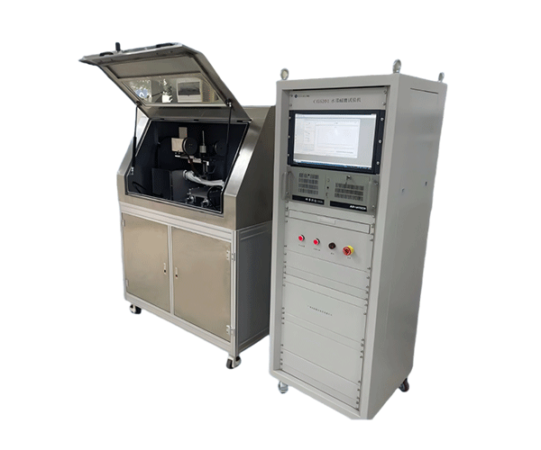
A Fire Hose Abrasion Resistance Test Apparatus applies a controlled rubbing action to a prepared specimen. The equipment may use an abrasive strip, rubbing surface, reciprocating movement, rotating fixture, or another arrangement defined by the test method. The specimen is held in a fixture so that the intended area is exposed to the abrasive contact.
Depending on the method, the test may involve a hose specimen that rotates, a rubbing tool that moves back and forth, or a localized contact point that concentrates wear on a specific area. Some procedures may require the specimen to be pressurized during testing, while others focus on the cover material under defined mechanical conditions. These arrangements are not interchangeable, and the selected method must be appropriate for the product.
The equipment helps control the factors that influence the test result. These can include the applied force, movement distance, movement frequency, abrasive material, contact position, specimen mounting, and number of cycles. Where required, the system can also include a counter, control panel, protective enclosure, and data recording functions.
We do not assume that every customer needs the same features. A laboratory testing semi-rigid fire hoses may need a different fixture and rubbing arrangement from a manufacturer testing layflat hoses. During customization, we review the test method and specimen design to determine which components are necessary.
Why is abrasion resistance important?
During real use, a fire hose may be pulled over rough ground, dragged around corners, or repeatedly moved between storage and operating positions. Even when the hose passes its pressure test, its outer surface may still need to withstand the physical contact associated with handling and deployment.
Abrasion resistance testing gives manufacturers a controlled way to evaluate this property. It can help answer practical questions: Does a new cover material resist surface wear better than the existing material under the same test conditions? Does one production batch behave differently from another? Does a design change introduce a weak area? Does the specimen show the type of damage described in the test method?
These questions are particularly useful during material selection and product development. If a manufacturer changes the outer cover compound, textile construction, coating, or production process, comparative abrasion testing can help show whether the change affects wear behavior.
For routine quality control, the test can also support batch comparison and defect investigation. If wear results begin to change, engineers can review material records, manufacturing parameters, surface finish, and other factors that may influence performance.
Abrasion resistance is not the same as overall durability
One important point is worth making clear: a hose that performs well in an abrasion test is not automatically suitable for every operating condition. Abrasion resistance is different from burst strength, pressure resistance, adhesion between layers, heat resistance, chemical resistance, aging performance, and low-temperature flexibility.
For example, a hose cover may resist rubbing well but still require separate testing for heat exposure or pressure performance. Likewise, a specimen that survives a short abrasion test may not have a predictable service life in every environment. The actual wear experienced in the field depends on many variables that a laboratory test may not reproduce.
We therefore treat abrasion resistance as one part of a wider product evaluation program. The equipment should answer the specific question it was designed to test, while other properties should be evaluated using their own suitable methods.
2. Working Principle and Typical Test Procedure
The principle of abrasion resistance testing is simple: expose a hose specimen to a defined rubbing action and evaluate the damage or performance change that occurs. The challenge is keeping the test conditions consistent. If the abrasive material, applied force, movement, or specimen setup changes between tests, the results may no longer be directly comparable.
For this reason, the equipment must be designed around the test method. A reciprocating abrasion tester for a semi-rigid hose, for example, may require a different fixture and motion arrangement from a machine intended to evaluate the outer cover of a rubber hose. We confirm the intended procedure before selecting the drive system and specimen holder.
Step 1: Identify the hose and test standard
Before preparing the sample, the operator identifies the hose type, construction, nominal diameter, specimen length, and applicable test specification. The test plan should establish which surface is being evaluated and whether the test is intended to simulate a particular form of contact.
The required abrasive material, contact force, movement distance, frequency, number of cycles, and acceptance criteria should come from the relevant standard or approved procedure. We do not recommend choosing these values based only on experience with a different hose type.
This first step is important because the term “fire hose abrasion test” can refer to different methods. A surface abrasion test may spread wear over a larger area, while a point abrasion test concentrates contact in a smaller region. A method designed for semi-rigid fire hoses may also differ from one used for non-percolating layflat hoses.
Step 2: Prepare and inspect the specimen
The sample is cut or prepared according to the relevant procedure. The specimen dimensions, conditioning requirements, and surface preparation should be consistent with the test plan. If the method requires multiple specimens or different test positions, these requirements should be followed.
Before testing, the operator checks the sample for visible defects and records any condition that may influence the result. The specimen should be identified so that its test record can be linked to the correct product, batch, or material formulation.
Sample preparation is not a minor detail. A specimen cut too short, mounted incorrectly, or taken from a damaged area may behave differently from a properly prepared sample. Consistent preparation helps make the test more repeatable and the results easier to interpret.
Step 3: Install the specimen and abrasive tool
The hose sample is installed in the fixture according to the test procedure. The fixture must hold the sample securely and maintain the intended contact position while allowing the required movement. The abrasive tool or strip is installed and aligned as specified.
Some methods require a specimen to rotate while the abrasive tool moves along its surface. Others use a stationary specimen with a reciprocating rubbing tool. Point abrasion methods may require the contact tool to act at defined positions around the hose surface.
The fixture and abrasive tool must be suitable for the specimen dimensions and the required contact force. If the test involves a pressurized sample, the pressure system, fittings, and protective arrangement must also be suitable for the specified conditions.
Step 4: Set the test parameters
Once the specimen is installed, the operator verifies the required settings. Depending on the method, these may include the applied force, movement frequency, stroke length, abrasive material, number of cycles, rotation speed, or sample pressure.
These values should not be treated as universal settings. Different standards can define different test arrangements and acceptance criteria. The equipment configuration should therefore allow the required parameters to be established and checked according to the selected method.
Where the machine includes electronic controls, the operator may be able to set the cycle count and monitor test progress from the control panel. The exact level of automation depends on the agreed equipment configuration.
Step 5: Run the abrasion test
After the setup has been checked, the test begins. The abrasive tool and specimen move relative to each other in the manner required by the procedure. The contact action gradually wears the test surface, allowing the operator to evaluate how the sample responds under controlled conditions.
During the test, the equipment may count cycles or strokes and stop when the specified endpoint is reached. The operator should monitor the machine for unusual noise, movement, specimen displacement, or other conditions that could affect the test or create a safety concern.
If the procedure defines a failure event, such as visible damage reaching a particular layer or a specimen losing its required integrity, that event must be identified according to the specified criteria. The operator should not replace the formal acceptance criteria with an informal visual judgment.
Step 6: Inspect the worn area and record the result
After the test, the specimen is removed and inspected according to the method. Depending on the procedure, the result may be based on the number of cycles completed before a defined failure, the appearance of the worn surface, the depth or extent of wear, or another specified measurement.
The test record should identify the specimen, test parameters, abrasive material, observed damage, and final result. If the test is repeated across several samples, each result should be recorded separately before calculating any average or applying the specified acceptance rule.
Photographs can be useful when comparing the appearance of worn areas, provided that the photography method is consistent. They can help engineers review surface damage, but photographs should not replace a numerical measurement or failure criterion when the standard requires one.
Table 1. Typical stages in a fire hose abrasion resistance test
| Stage | Main objective | Information to control or record |
|---|
| Sample identification | Confirm which hose is being tested | Hose type, batch, dimensions, specimen ID |
| Specimen preparation | Prepare a representative sample | Length, conditioning, surface condition, test position |
| Fixture installation | Position the specimen correctly | Mounting method, alignment, contact area |
| Parameter setup | Apply the specified abrasion conditions | Force, stroke, frequency, abrasive type, cycle count |
| Test operation | Apply repeated controlled contact | Cycles completed, interruptions, abnormal events |
| Post-test inspection | Evaluate wear or failure according to the method | Damage observations, failure point, result, photographs if required |
Source note: This table summarizes a general laboratory workflow and is not a verbatim procedure from one standard. The actual specimen dimensions, test parameters, and acceptance criteria must be taken from the applicable product standard or approved test method. EN 15889:2011, “Fire-fighting hoses — Test methods,” includes defined surface and point abrasion methods for semi-rigid fire-fighting hoses within its scope.
3. Main Features and Customization Options
When selecting a Fire Hose Abrasion Resistance Test Machine, it is tempting to compare only the maximum load or the number of cycles the machine can perform. In practice, the most important question is whether the equipment can reproduce the required test conditions and hold the specimen in the correct position.
We design customized testing equipment around the intended procedure. The following functions are common considerations during equipment planning. The final configuration depends on the hose type, standard, test parameters, and customer's workflow.
Controlled abrasion movement
The drive system creates the relative movement between the specimen and abrasive tool. Depending on the test method, this may involve reciprocating movement, specimen rotation, or a combination of movements.
The movement needs to be repeatable. If the stroke length or movement frequency changes unexpectedly, the contact conditions may change as well. A suitable drive arrangement helps maintain the prescribed motion and supports consistent comparisons between specimens.
During customization, we confirm the required movement pattern, stroke length, frequency, and cycle count. These details determine the drive mechanism, transmission components, control method, and fixture arrangement.
Adjustable specimen fixtures
Fire hoses come in different diameters and constructions, so the fixture must suit the sample. A fixture designed for a semi-rigid hose may not be appropriate for a flexible layflat hose. The specimen may need to be supported, rotated, or held in a particular orientation to reproduce the test conditions.
Where several hose sizes need to be tested, adjustable fixtures may be considered. For a narrow product range, a dedicated fixture can sometimes provide a simpler arrangement. The decision depends on the specimen geometry, the required accuracy of positioning, and the expected testing workload.
We recommend providing drawings and sample photographs before ordering. These materials help us understand the contact area, sample movement, and any special support requirements.
Abrasive tool and contact-force control
The abrasive material and contact force strongly influence the result. A harder abrasive surface or a higher force may produce more severe wear, but that does not automatically make the test more useful. The purpose is to reproduce the conditions defined by the selected test method.
The abrasive tool must also be installed correctly and replaced or renewed according to the applicable procedure. If the abrasive surface becomes worn or contaminated, the contact behavior may change and affect the comparison between samples.
Where the method specifies a defined force, the machine should provide a suitable arrangement to apply and maintain it. We confirm the required force range and adjustment method during technical review rather than assuming a single value for all hoses.
Cycle counting and automatic stopping
A cycle counter helps operators track the amount of abrasion applied to a sample. Depending on the test procedure, the machine may be set to stop after a defined number of cycles or continue until an identified failure event occurs.
Automatic stopping can make routine testing easier, particularly when multiple specimens are evaluated. However, the endpoint must be defined correctly. If the method requires an operator to inspect the sample for a particular type of damage, cycle counting alone cannot determine whether the specimen has passed.
We discuss whether the customer needs manual control, preset cycle counting, automatic stopping, or a more advanced control arrangement. The objective is to support the test method without adding unnecessary complexity.
Protective enclosure and operator safety
Abrasive testing involves moving mechanical parts and may produce small particles or debris from the specimen and abrasive tool. A suitable protective enclosure can help reduce operator exposure and keep debris within the test area.
Where the method requires a pressurized hose specimen, the safety assessment must also consider the pressure system and the possibility of specimen failure. Guards, emergency stopping, safe access, and other protective measures should be selected according to the equipment design and the risks associated with the test.
Operators should receive suitable training and follow the operating instructions. The machine should not be operated with guards removed or safety devices bypassed. Any maintenance or adjustment should be carried out according to the defined safe procedure.
Data recording and test reporting
Some customers need a simple cycle counter and manual result sheet. Others may require electronic records, test progress monitoring, sample identification, or data export. The required functions depend on the laboratory's workflow and the way results are used.
We recommend deciding in advance which information needs to appear in the final record. Typical fields include specimen ID, test method, abrasive material, applied force, stroke length, frequency, number of cycles, observations, and final result.
Where a test requires the number of cycles completed before failure, the equipment and procedure should make that endpoint clear. If the test instead relies on a defined inspection of surface damage, the record should include the observations or measurements required by the method.
Table 2. Configuration options for fire hose abrasion testing
| Configuration item | Purpose | What to confirm before ordering |
|---|
| Drive mechanism | Produces the specified rubbing movement | Movement type, stroke length, frequency, rotation requirements |
| Specimen fixture | Holds and positions the hose sample | Diameter, sample length, flexibility, mounting orientation |
| Abrasive tool | Creates the required contact surface | Abrasive type, dimensions, replacement procedure |
| Force adjustment | Applies the specified contact force | Required force range and method of verification |
| Cycle counter | Tracks test movement | Cycle definition, preset count, stop conditions |
| Protective enclosure | Helps protect the operator during testing | Moving parts, debris, specimen failure risks |
| Data recording | Supports traceability and result review | Required fields, report format, data export needs |
Source note: This table is a practical equipment-selection guide prepared for this product page. It is not a mandatory feature list from a standard. Final equipment specifications should be confirmed against the applicable test method and project-specific risk assessment.
4. Standards, Test Methods, and Result Interpretation
Standards are important because abrasion resistance results are meaningful only when the test conditions and acceptance criteria are understood. A test using one abrasive material, contact force, and movement pattern cannot automatically be compared with a test using a different method.
Fire hoses are divided into different product categories, and their abrasion tests can differ. Some methods focus on semi-rigid fire hoses. Others cover the outer covers of rubber or plastics hoses more generally. Certain product specifications define abrasion procedures for non-percolating layflat fire hoses. We therefore recommend identifying the exact hose category before choosing the test apparatus.
EN 15889: Fire-fighting hoses — Test methods
EN 15889:2011 is a standard covering test methods for fire-fighting hoses. Its annexes include a surface abrasion resistance test for semi-rigid fire-fighting hoses and a point abrasion resistance test for the same general category. It also addresses other properties, such as adhesion, kink pressure, accelerated aging, and low-temperature flexibility.
The distinction between surface abrasion and point abrasion is useful when planning equipment. Surface abrasion evaluates wear over a defined contact area, while point abrasion concentrates the rubbing action at a particular location. The two tests can reveal different aspects of how a hose cover responds to mechanical contact.
The standard's scope matters. A method written for semi-rigid fire-fighting hoses should not automatically be applied to every layflat hose or industrial hose. The applicable clauses and current edition should be checked before equipment specifications are finalized.
ISO/TS 20444:2024 — Abrasion resistance of the outer cover
ISO/TS 20444:2024 specifies a method for determining the abrasion resistance of the outer cover of rubber and plastics hoses. According to the ISO catalogue, the method is suitable for hoses with inside diameters from 10 mm to 38 mm and is intended for comparing products with similar cover materials.
The scope also makes an important limitation clear: this method is not intended to predict the service life of a product. It can help compare abrasion behavior under defined test conditions, but the results should not be converted directly into a number of years or months of field use.
For customers considering this method, the suitability of the standard must be checked against the actual hose construction and intended application. It may be relevant to certain hose-cover materials, but it should not be assumed to replace a product-specific fire hose abrasion test.
Product-specific standards for layflat and other fire hoses
Non-percolating layflat fire hoses may be covered by different product standards and abrasion procedures from those used for semi-rigid hoses. For example, published regulatory material referring to layflat firefighting hoses with internal diameters between 25 mm and 52 mm identifies abrasion test provisions in NF S 61-112 and DIN 14811 for the stated category.
This is a reminder that product type, diameter, intended use, and market requirements can affect the selected test. A test procedure for a hose used in a fixed fire protection system may not be identical to one intended for fire-fighting vehicles or another application.
We recommend that customers provide the exact standard and edition whenever possible. If the test requirement is specified in a customer document or technical agreement, that document should also be reviewed to confirm the abrasive tool, contact force, cycle definition, and acceptance criteria.
Table 3. Examples of abrasion-related standards and their scope
| Reference | Product or test area | Potential relevance | Key limitation |
|---|
| EN 15889:2011 | Fire-fighting hose test methods, including surface and point abrasion for semi-rigid hoses | Helps define abrasion testing arrangements for products within its scope | Do not assume its abrasion methods apply to every hose construction |
| ISO/TS 20444:2024 | Abrasion resistance of the outer cover of rubber and plastics hoses | Supports comparison of like-cover material products under a defined method | ISO identifies a suitable inside-diameter range of 10–38 mm and states that the method is not intended to predict service life |
| DIN 14811 | Fire-fighting hoses covered by the applicable edition and product scope | May be relevant to specified abrasion requirements for certain layflat fire hoses | Verify the applicable edition, hose category, and relevant clauses |
| NF S 61-112 | Fire hoses covered by the applicable French specification | May define abrasion requirements for specified non-percolating layflat fire hoses | Confirm the applicable version and exact product requirements |
Sources: ISO, ISO/TS 20444:2024 — Rubber and plastics hoses: Determination of abrasion resistance of the outer cover; Standards Information System of Serbia, SRPS EN 15889:2012 — Fire-fighting hoses: Test methods; EUR-Lex, published technical material listing abrasion testing standards for specified layflat firefighting hoses. Consult the full applicable standard and current edition before setting test parameters or acceptance criteria.
How should abrasion test results be interpreted?
The result depends on what the method is designed to measure. Some procedures use the number of cycles completed before a defined failure. Others assess the condition of the worn surface or compare the extent of abrasion after a specified exposure. The correct result format comes from the applicable procedure.
It is important not to mix different types of results. For example, a higher cycle count before a defined failure may indicate better performance within that specific test, but it cannot automatically be compared with a wear-depth measurement from another method. Similarly, a test using a different abrasive material or force may produce results that are not directly comparable.
For a fair comparison, test samples should be prepared and tested under the same conditions. The same abrasive material, contact force, movement pattern, cycle definition, and inspection method should be used wherever the procedure requires them to remain constant.
We also recommend recording the failure mode, not just the final number. A surface may show scuffing, local thinning, cracking, or exposure of an underlying layer. These observations can help engineers understand why two samples produced different results and whether a manufacturing change requires further investigation.
5. Applications in Fire Hose Manufacturing and Quality Control
Abrasion resistance testing can support several stages of the fire hose manufacturing process. It is useful for product development, material comparison, production quality control, and investigation of wear-related defects. The exact test setup depends on the hose type and the product specification.
Fire hose manufacturers
Manufacturers may use abrasion resistance testing to evaluate the performance of outer covers and compare different hose constructions. If a new cover material is introduced, testing can help determine whether its wear behavior differs from that of the existing design under the same conditions.
The equipment can also support routine checks on production samples. If results begin to change, engineers can review material batches, processing conditions, cover thickness, reinforcement construction, and other factors that may influence abrasion behavior.
Testing does not replace process control or visual inspection, but it provides a defined method for evaluating a property that can be difficult to judge consistently by eye alone.
Fire hose reel and semi-rigid hose suppliers
Semi-rigid hoses used on fire hose reels and fire-fighting vehicles may be subject to surface or point abrasion test methods, depending on the applicable product standard. A suitable abrasion tester can help suppliers and manufacturers evaluate the relevant surface wear characteristics under controlled conditions.
For this category, specimen rotation, rubbing movement, support rollers, contact force, and the type of abrasive strip may be important parts of the test arrangement. The machine must be designed to reproduce the required method, rather than relying on a generic rubbing mechanism.
Layflat fire hose manufacturers
Layflat hoses are designed to be flexible and can be stored or transported in a flattened condition. During use, they may be dragged across the ground or come into contact with rough surfaces. The abrasion test method for a particular layflat hose may differ from the one used for a semi-rigid hose.
For this reason, we ask customers to identify the exact hose category, diameter, construction, and standard. If the relevant method requires a particular sample condition or a defined number of cycles before failure, those requirements need to be reflected in the equipment configuration.
Third-party testing laboratories
Testing laboratories may need abrasion equipment that produces repeatable motion and allows operators to maintain consistent sample preparation and test conditions. Depending on their scope, laboratories may evaluate several hose categories or focus on a specific product family.
For laboratory use, we recommend confirming the required abrasive tools, specimen fixtures, force range, cycle counting, data recording, and maintenance procedures before ordering. If the results are used within an accredited laboratory or formal quality system, the laboratory must also review the equipment and test method against its own requirements.
Purchasing an abrasion resistance test machine does not by itself provide laboratory accreditation or certify the hose. The test method, equipment suitability, measurement controls, and product evaluation process all remain important.
Material research and product development
Engineers may use abrasion tests when comparing rubber compounds, polymer covers, coatings, textile constructions, or other surface materials. A controlled test can help show whether one design behaves differently from another when exposed to the same rubbing conditions.
To obtain useful comparison data, it is best to change one factor at a time where practical. If the material, thickness, abrasive tool, contact force, and cycle count all change at once, it becomes difficult to identify the reason for a difference in results.
A well-planned test program can help product developers screen material options, identify possible weak points, and decide which designs need further testing. The results should still be interpreted within the limits of the test method and should not be treated as a direct prediction of real-world hose life.
Quality inspection and supplier evaluation
Some organizations need to compare hoses supplied by different manufacturers or monitor changes between production batches. A defined abrasion test can provide one consistent source of information, provided that the samples are tested under the same procedure.
When comparing suppliers, the test specification should be agreed in advance. It should define the hose category, sample preparation, abrasive material, contact conditions, test endpoint, and acceptance criteria. Without this common basis, two test reports may appear different simply because the methods are not the same.
6. Our Customization Process, Manufacturing, and Delivery
At Guangzhou Chuangge Automation Equipment Co., Ltd., we know that a customized testing machine must fit the customer's product and test method. A machine may have a powerful motor and a convenient control panel, but it will not provide useful results if the fixture is unsuitable, the rubbing motion is incorrect, or the abrasive tool does not match the procedure.
We specialize in customized testing equipment for industrial applications, including construction materials and components, wires and cables, plastics and textiles, electrical plugs, sockets and switches, electronic products, and household appliances. Our experience with different testing applications helps us approach each project by first understanding the required measurement and then planning the appropriate equipment configuration.
Step 1: Discuss the test requirements
We begin by understanding the hose type, test purpose, and applicable standard. Important details include the specimen dimensions, outer cover material, test method, abrasive tool, contact force, movement pattern, cycle count, and acceptance criteria.
Drawings, photographs, technical datasheets, and sample information are useful at this stage. They help us understand the physical construction and identify any special fixture or support requirements.
If the customer intends to test several hose types, we recommend providing the requirements for each one. This allows us to determine whether a common configuration is practical or whether different fixtures or test arrangements will be necessary.
Step 2: Confirm the equipment design
After the technical requirements are reviewed, we prepare the proposed configuration. Depending on the test method, this may include the drive system, specimen fixture, abrasive tool holder, force adjustment, cycle counter, protective enclosure, and control interface.
We consider how the components work together. The drive mechanism must provide the required movement, the fixture must hold the sample correctly, and the abrasive tool must contact the intended area. If the test requires a pressurized specimen, the pressure arrangement and associated safety measures must also be considered.
At this stage, we also discuss the expected testing workload, installation space, operating environment, power supply, and data recording requirements. These details help make the final equipment suitable for routine use.
Step 3: Component preparation and assembly
Once the technical configuration and commercial terms are agreed, the project moves into manufacturing and assembly. Components are prepared according to the approved design, and the mechanical, control, and safety-related systems are integrated.
The exact manufacturing process depends on the selected configuration and the level of customization. We confirm the relevant components and functions for each project rather than assuming that every abrasion tester requires an identical build.
For customized equipment, clear identification of components and practical maintenance documentation are useful for later operation. They help users understand the machine layout and support routine inspection and troubleshooting.
Step 4: Functional inspection and performance verification
Before delivery, each unit undergoes functional inspection and performance verification within the agreed scope. These checks help confirm that the assembled equipment operates as intended and that the relevant functions can be demonstrated under the defined verification conditions.
Depending on the configuration, the agreed checks may cover drive movement, cycle counting, fixture operation, control functions, or other key items. The exact verification scope should be confirmed before production begins.
Functional inspection is not automatically the same as formal calibration, third-party certification, or proof that a customer's hose complies with a particular product standard. If the project requires formal calibration records, traceability documentation, witnessed acceptance testing, or other specific deliverables, those requirements should be discussed during the quotation stage.
Step 5: Documentation and packing
We provide technical documentation as agreed with the customer. Depending on the project, this may include equipment information, operating instructions, maintenance guidance, and relevant inspection or verification records.
After the agreed inspection is completed, the equipment is prepared for transport using protective packaging and sturdy wooden cases where appropriate. The packing arrangement is selected according to the equipment structure, size, and shipping requirements.
Production cycle and shipping arrangements
Our typical production cycle for customized testing equipment is approximately 30 to 60 days. This is a general planning estimate, not a fixed lead time for every project. The actual schedule depends on the specifications, degree of customization, component availability, design confirmation, and any additional inspection or documentation requirements.
We can arrange sea, air, or land transportation according to the destination, delivery schedule, equipment size, and customer preference. Payment terms are negotiable and confirmed in the commercial agreement.
For customers working toward a fixed delivery date, we recommend confirming the technical details as early as possible. Changes to the test method, fixture dimensions, abrasive tool, control functions, or documentation after production begins may affect the project schedule.
Why choose Guangzhou Chuangge Automation Equipment Co., Ltd.?
We focus on customized industrial testing equipment and believe that understanding the test requirements is the starting point for a suitable design. Our company follows the philosophy of ensuring survival through high technology and driving development through high quality.
We have obtained ISO 9001 quality management, ISO 14001 environmental management, and ISO 45001 occupational health and safety management system certifications. Our intellectual property portfolio includes more than 20 patents, including invention patents, utility model patents, and software patents.
These credentials form part of our company's technical background. For each project, however, we focus on the practical details that determine whether the machine suits the customer's needs: the correct test method, appropriate specimen fixtures, controlled rubbing movement, suitable contact conditions, operator safety, and useful test records.
We work with customers to clarify these requirements before confirming the equipment design. Our goal is to supply customized testing equipment that supports the customer's quality workflow and provides a consistent basis for evaluating the specified abrasion resistance characteristics.
7. Frequently Asked Questions About Fire Hose Abrasion Testing
Q1. What does an abrasion resistance test measure?
An abrasion resistance test evaluates how a hose surface or specified component responds to repeated rubbing under defined conditions. Depending on the method, the result may be based on cycles completed before failure, visible surface damage, or another specified measurement. The correct endpoint and acceptance criteria come from the applicable standard or approved test procedure.
Q2. Can one machine test all types of fire hoses?
Not automatically. Layflat hoses, semi-rigid hoses, and other hose constructions can require different fixtures, movement patterns, abrasive materials, and test conditions. A single machine may support multiple products if the configuration is suitable for each required method. We recommend providing the full list of hose types and standards before equipment selection.
Q3. What is the difference between surface abrasion and point abrasion?
Surface abrasion evaluates wear across a defined contact area, while point abrasion concentrates contact at a smaller location. The methods can reveal different aspects of hose cover behavior. They should not be treated as interchangeable, and the correct method depends on the hose category and applicable product standard.
Q4. Can the test predict how many years a fire hose will last?
Not by itself. Abrasion testing provides information about the specimen's behavior under defined laboratory conditions. Real service life also depends on handling, storage, pressure cycles, environmental exposure, maintenance, and the types of surfaces encountered in use. Some standards explicitly state that their abrasion method is intended for comparing similar materials rather than predicting product life.
Q5. Which standard should I use for fire hose abrasion testing?
The answer depends on the hose type and intended application. EN 15889 includes surface and point abrasion methods for semi-rigid fire-fighting hoses. ISO/TS 20444:2024 covers abrasion resistance of the outer cover of rubber and plastics hoses within its stated scope. Layflat fire hoses may be subject to different product-specific requirements. Always confirm the exact standard, edition, and test clause.
Q6. Can the equipment be customized for a specific hose diameter?
Yes, customization can be discussed based on the sample dimensions and test method. Please provide the hose diameter, specimen length, construction, fixture requirements, and applicable standard. We can then review the suitable specimen holder, drive arrangement, and other configuration details.
Q7. Can the machine record the number of abrasion cycles?
A cycle counter can be included when required by the project. The counter configuration should match the cycle definition in the test procedure, particularly where the method distinguishes between a single stroke and a complete cycle or double stroke. Automatic stopping may also be considered if the test endpoint is defined by a preset count.
Q8. Does the equipment automatically determine whether a hose passes or fails?
That depends on the test method and the agreed control functions. The equipment can count cycles and support test recording, but some acceptance criteria require inspection of the worn area or identification of a specific failure event. The pass/fail decision must follow the applicable standard and should not rely on an unrelated automatic setting.
Q9. What information should I provide when requesting a quotation?
To help us evaluate your project, please provide the following information where available:
Hose type, construction, nominal diameter, and specimen length.
Applicable test standard, edition, or customer test procedure.
Required abrasion method, such as surface abrasion or point abrasion.
Abrasive material, contact force, movement pattern, and stroke requirements.
Required cycle count or the failure condition used as the test endpoint.
Whether the specimen needs to be pressurized during the test.
Required fixtures, control functions, cycle counting, and data recording.
Expected testing workload, operating environment, and safety requirements.
If you do not have every parameter available, you can send us the hose drawings, product datasheet, standard reference, or photographs first. We can use this information to identify which details need to be confirmed before the design is finalized.
Q10. How long does production take?
The typical production cycle is approximately 30 to 60 days, depending on the specifications and degree of customization. The actual lead time is confirmed after the technical requirements are reviewed. Special fixtures, additional control functions, and particular inspection or documentation requirements may affect the schedule.
Q11. Does the equipment include calibration certificates?
Functional inspection and performance verification are carried out before delivery according to the agreed scope. Formal calibration certificates are a separate requirement and should not be assumed unless they are explicitly included in the quotation or contract. If calibration, traceability, or third-party verification is needed, please specify it during the initial technical discussion.
Q12. How is the machine packed and shipped?
We use protective packaging and sturdy wooden cases where appropriate to help protect the equipment during transport. Sea, air, and land shipping options can be discussed according to the destination and project requirements. The final packing method, shipping arrangement, and documentation are confirmed with the customer before dispatch.
Conclusion: A Practical Solution for Fire Hose Abrasion Resistance Testing
Abrasion resistance testing helps manufacturers and laboratories understand how a fire hose surface responds to controlled mechanical wear. When the correct test method is used, the results can support material comparison, product development, production quality control, and investigation of wear-related defects.
At Guangzhou Chuangge Automation Equipment Co., Ltd., we develop customized testing equipment based on the customer's hose type and test requirements. For an Abrasion Resistance Test for Fire Hoses, we focus on the elements that matter in daily testing: specimen fixtures, abrasive tools, movement control, contact conditions, cycle counting, safety provisions, and result recording.
Our typical production cycle is 30 to 60 days, depending on the equipment specifications and customization requirements. Before delivery, each unit undergoes functional inspection and performance verification within the agreed scope. Technical documentation, protective packaging, and shipping arrangements are confirmed as part of the project.
If you are looking for a Fire Hose Abrasion Resistance Test Machine for product development, manufacturing quality control, or laboratory evaluation, contact our team with your hose specifications and applicable test procedure. We can discuss the required method, clarify the equipment configuration, and prepare a customized proposal suited to your application.
Contact Guangzhou Chuangge Automation Equipment Co., Ltd. to discuss your fire hose abrasion testing requirements and request a customized equipment proposal.
Reference Sources
International Organization for Standardization (ISO), ISO/TS 20444:2024 — Rubber and plastics hoses: Determination of abrasion resistance of the outer cover. View the official ISO page.
Standards Information System of Serbia, SRPS EN 15889:2012 — Fire-fighting hoses: Test methods. View standard information and scope.
EUR-Lex, published technical material listing abrasion test standards for specified non-percolating layflat firefighting hoses. View the document.
RISE, hose testing services and examples of product and test standards used for hose evaluation. View hose testing information.
Technical note: The references above help identify potentially relevant test methods. Applicability depends on hose construction, diameter, intended use, market requirements, and the exact standard edition. Confirm the full applicable standard before defining test parameters or making product compliance claims. Abrasion test results should not be interpreted as a direct prediction of service life.


