<span style="font-size: 16px;"><a href='https://int.cgtesting.cn/tag/circuit-breaker-tripping-test-device' target='_blank' class='key-tag'><font><strong>Circuit Breaker Tripping Test Device</strong></font></a> for Electrical Protection Testing</span>Circuit Breaker Tripping Test Device for Reliable Electrical Protection Testing
A circuit breaker is a small but important part of an electrical protection system. When a circuit operates normally, the breaker allows current to pass through. When an overload, short circuit, or another defined fault condition occurs, the protection system must respond as designed and disconnect the circuit when required. If the breaker does not trip when expected, or if its operating behavior falls outside the specified limits, electrical equipment and connected systems may be exposed to unnecessary risk.
That is why circuit breaker testing is an important part of electrical equipment manufacturing, inspection, maintenance, and quality control. It helps engineers and technicians check whether a breaker and its associated tripping mechanism respond in accordance with the applicable test procedure. A suitable Circuit Breaker Tripping Test Device provides a structured way to carry out these checks and record the results.
At Guangzhou Chuangge Automation Equipment Co., Ltd., we specialize in customized testing equipment for industrial applications. Our work covers different sectors, including electrical products, electronic equipment, wires and cables, plastics, textiles, construction materials, and home appliances. We understand that testing requirements can vary considerably between products, so we focus on the actual test objective, applicable standards, operating conditions, and customer requirements when discussing a new equipment project.
Our Circuit Breaker Tripping Test Device concept is intended for applications that require controlled evaluation of circuit breaker tripping functions. Depending on the selected configuration, the equipment may be designed to support specified test sequences, controlled test inputs, response observation, data collection, and result recording. The precise functions depend on the breaker type, test method, electrical ratings, and technical specification agreed upon for the project.
We do not assume that one test device can perform every circuit breaker test. A low-voltage molded-case circuit breaker, an air circuit breaker, a residual-current device, and a high-voltage circuit breaker may require very different test arrangements. The first step is therefore to identify what the customer needs to test and how the results will be evaluated.
In this product page, we explain how a Circuit Breaker Tripping Test Device can be used, what technical factors matter when selecting one, and how we approach customized equipment development. Our goal is to help customers make a more informed decision before requesting a quotation.
1. What Is a Circuit Breaker Tripping Test Device?
Understanding the role of circuit breaker tripping tests
A circuit breaker is designed to make, carry, and interrupt current under specified operating conditions. Depending on its design, it may include thermal protection, magnetic protection, electronic protection, residual-current protection, or a combination of functions. When a defined condition occurs, the protection mechanism initiates a trip operation that opens the contacts and interrupts the circuit.
The tripping process sounds simple, but several parts must work together. The sensing element must respond to the relevant condition, the trip mechanism must operate, and the switching contacts must open as intended. In breakers with electronic trip units, the measurement and control electronics also play an important role. A test therefore needs to be designed around the function being evaluated rather than relying on a general visual inspection alone.
A Circuit Breaker Tripping Test Device is testing equipment intended to support checks of the breaker's tripping response under defined conditions. Depending on the equipment design, the test may involve applying a specified input, monitoring the trip operation, measuring a response time, or recording the result against a defined acceptance criterion.
For example, a manufacturer may need to check whether a low-voltage breaker responds appropriately to a specified overcurrent test condition. A maintenance team may want to investigate whether a breaker operates consistently with its documented settings. A quality inspection department may need to record test results for several units during production. Each application has a different objective, so the test method and equipment configuration should be selected accordingly.
What does a tripping test actually verify?
The answer depends on the breaker design and the test procedure. A tripping test may evaluate one or more of the following:
Whether the specified tripping function responds under the defined test condition.
Whether the breaker operates within the required time or response range.
Whether an adjustable protection setting behaves according to the applicable procedure.
Whether the trip mechanism and associated control circuit operate as expected.
Whether test results remain consistent when the same defined procedure is repeated.
Whether the observed response meets the specified acceptance criteria.
Not every Circuit Breaker Tripping Test Device measures all these items. Some systems focus on a specific trip function, while others may support several procedures through different test arrangements or configurations. The final equipment scope should identify which breaker types, protection functions, test inputs, measurement channels, and output records are included.
It is also important to distinguish a tripping test from a complete circuit breaker type test. A tripping test may be one part of a broader evaluation, but it does not automatically verify every electrical, mechanical, thermal, dielectric, or short-circuit performance requirement of a breaker.
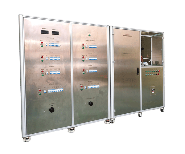
Why manufacturers and maintenance teams need this equipment
During production, a circuit breaker may need to pass defined inspection steps before it can be released. A repeatable test arrangement helps the manufacturer follow the same procedure across multiple units and compare the results with established requirements.
In maintenance work, testing can help identify changes in operating behavior. A breaker that has been in service may require inspection after a fault, after maintenance, or as part of a scheduled condition assessment. The appropriate procedure depends on the equipment manufacturer's instructions, the system requirements, and the applicable safety rules.
For laboratories and inspection institutions, the emphasis may be on a controlled test method, suitable measuring equipment, documented results, and a clearly defined evaluation process. For all these users, a properly specified Circuit Breaker Trip Test Equipment solution can help organize testing work and reduce dependence on informal manual procedures.
Our approach to product customization
At Guangzhou Chuangge Automation Equipment Co., Ltd., we start by asking what the customer needs to prove. We review the breaker type, rated values, trip functions, applicable test requirements, and desired result format before discussing the equipment structure.
We also need to understand whether the application involves production-line inspection, laboratory testing, repair verification, or routine maintenance. A system designed for frequent testing of a specific breaker model may use a different fixture and operating sequence from equipment intended to support several models in a laboratory.
This approach helps us avoid a common purchasing problem: choosing a device based only on its product name and discovering later that its current range, connection arrangement, trip function, or reporting capability does not match the actual requirement.
2. Working Principle: How Does a Circuit Breaker Tripping Test Work?
Step 1: Identify the breaker and its protection function
Before selecting a test method, the operator needs to identify the circuit breaker. Important information includes the manufacturer, model, rated voltage, rated current, trip unit type, available settings, and relevant technical documentation. Where applicable, the operator should also identify the protection functions that need to be evaluated.
This step matters because circuit breakers do not all respond in the same way. A thermal-magnetic breaker may use a thermal element for overload protection and a magnetic mechanism for high-current fault protection. An electronic trip unit may use current sensors and an electronic control circuit to apply defined trip settings. A residual-current device operates according to a different principle and requires an appropriate test method for its residual-current function.
Even when two breakers have similar external dimensions, their internal protection mechanisms and test requirements may differ. The product name alone is therefore not enough to determine whether a particular test device is suitable.
Step 2: Define the test objective and acceptance criteria
The next step is to define exactly what will be tested. Is the goal to check a trip function, measure operating time, verify a particular setting, or perform a more extensive inspection procedure? The answer determines the required test input, measurement method, and result format.
The acceptance criteria must also be clear. A test result cannot be judged correctly without knowing the applicable limit or requirement. The permitted response may depend on the breaker rating, trip curve, selected setting, test condition, and governing standard or manufacturer specification.
We recommend confirming these details before equipment design begins. If a customer has a written test procedure, product standard, or internal inspection specification, it should be reviewed as part of the technical discussion. This reduces the risk of designing a system that performs a measurement but cannot support the intended quality decision.
Step 3: Establish a suitable test arrangement
A circuit breaker tripping test requires a suitable way to create or simulate the defined test condition and observe the response. Depending on the procedure, this may involve a controlled electrical input, a dedicated test source, a connection fixture, a signal interface, or other test equipment.
The arrangement must be suitable for the electrical ratings and test objective. A system designed for low-voltage breaker testing should not be assumed to support high-voltage switching equipment. Similarly, a device intended to evaluate an electronic trip unit may not be suitable for testing every thermal, magnetic, residual-current, or mechanical function.
Electrical safety is especially important. Test arrangements must account for the possible presence of hazardous voltages and currents, stored energy, unexpected switching, and the risk of accidental contact. The operator should follow the equipment instructions, the breaker manufacturer's requirements, and the applicable site safety procedures.
Step 4: Connect the equipment and check the setup
After the test arrangement has been selected, the breaker is connected according to the approved procedure. Connection points, test leads, control interfaces, and any required auxiliary supplies must be checked before the test starts.
The operator should confirm that the breaker is in the required state, that the selected settings match the procedure, and that the test equipment is configured correctly. Incorrect connections or settings can produce misleading results and may create unnecessary safety risks.
For customized equipment, we consider the connection arrangement and operator workflow during the design stage. Depending on the project, this may include dedicated terminals, model-specific fixtures, clear connection markings, protective enclosures, or a defined sequence for setup confirmation. The exact functions are established according to the agreed technical requirements.
Step 5: Apply the defined test condition
Once the setup has been checked, the operator or configured control system applies the test condition required by the procedure. The test may examine a specified trip function or a defined operating point. The exact input and duration must be based on the relevant test method, not on an arbitrary value chosen for convenience.
In some configurations, a test system may control the input and coordinate the test sequence. In others, the operator may carry out some steps manually. Whether the system can automatically generate test inputs, switch test states, or execute multiple test points depends on its design and should be confirmed before purchase.
For tests involving significant electrical energy, the arrangement must be designed to suit the required conditions. A small signal test, a secondary injection test, and a test involving the main current path are not interchangeable methods. They can assess different parts of the protection system and have different limits.
Step 6: Observe the trip response and collect results
During the test, the system needs a defined way to identify the relevant response. Depending on the test method, this may involve observing contact status, measuring elapsed time, monitoring an electrical signal, or recording a trip indication.
Where timing is required, the start event and stop event must be defined consistently. For example, the measured interval may depend on when the test input begins and when a specified trip indication or contact event is detected. Different measurement definitions can produce different results, so the procedure must state what the recorded time represents.
If the selected configuration includes automatic data acquisition, the system may collect compatible signals and associate them with the relevant test step. If not, readings may need to be recorded by the operator. We recommend defining the required data fields before production, especially when test records must be transferred into an existing quality system.
Step 7: Compare the result with the requirement
Once the test is complete, the result is compared with the applicable acceptance criterion. Depending on the procedure, this may involve a trip/no-trip outcome, a measured operating time, a current threshold, or another defined result.
A result outside the specified range does not automatically identify the cause. Possible explanations may include incorrect settings, a connection problem, a test setup issue, a fault in the breaker, or a problem in the test equipment. The next step should follow a documented troubleshooting procedure rather than assuming that the breaker itself is defective.
Where the configured software supports automatic evaluation, the system may compare the recorded result with a pre-entered limit and display a pass/fail indication. This can help standardize routine inspection, but the acceptance limits must be correct, current, and appropriate for the breaker under test.
Step 8: Save the test record and complete the procedure
Test records help manufacturers and maintenance teams track what was tested, under which conditions, and with what result. Depending on the application, a record may include the breaker model, serial number, rated values, selected settings, test method, measured values, acceptance limits, date, and operator information.
Where the equipment includes reporting functions, these fields may be organized into a digital record or exported in an agreed format. The actual report fields and export options depend on the final configuration.
For us, a useful Circuit Breaker Tripping Test Device should support a clearly defined test process from setup to result review. Automation is most valuable when it makes the work more consistent, reduces repetitive handling, and helps users produce records that can be understood and checked later.
3. Main Features and Technical Advantages
Defined test procedures for consistent operation
Repeated testing is easier to manage when the steps are clearly defined. Without a structured procedure, different operators may select different settings, follow slightly different sequences, or record results in different ways. These differences can make it harder to compare test results across a production batch or between inspection periods.
A suitably configured Circuit Breaker Tripping Test Device can help standardize the workflow. Depending on the design, it may provide a guided test sequence, defined input settings, clear prompts, and a structured method for recording results. These functions are particularly useful when the same type of test is carried out repeatedly.
Standardization does not mean that every breaker should receive the same test values. The correct values still depend on the breaker model, protection function, rating, settings, and applicable procedure. A good workflow makes those differences clear rather than hiding them behind a single generic test button.
Trip response evaluation
The central purpose of tripping test equipment is to evaluate the response required by the selected test procedure. Depending on the application, the relevant response may be whether the breaker trips, when it trips, or how it behaves at a defined test point.
Where time measurement is part of the specification, the system should use an appropriate measurement method and a clearly defined event. The measuring capability must be suitable for the response time being evaluated. We therefore recommend discussing the required time range, resolution, accuracy, and trigger definition before confirming a design.
These values should not be guessed from the product category. A system intended for one kind of breaker may have different measurement requirements from a system intended for another. The equipment specification should state the supported test functions and relevant performance limits clearly.
Support for configurable test parameters
Some circuit breakers have adjustable protection settings. Depending on the type of breaker and the selected test procedure, the user may need to verify performance at specific settings or test points. A configurable test system can help organize these operations when the necessary functions are included in the design.
However, configurable does not mean universally compatible. The system must be able to create or measure the conditions required by the particular breaker. It must also use the correct procedure and limits. A test program for one trip unit should not be applied to another without confirming its suitability.
During customization, we discuss which parameters the operator needs to select, which values should be fixed by the procedure, and which results must be recorded. This helps make the equipment practical for the intended work rather than unnecessarily complicated.
Data acquisition and digital records
Data recording becomes important when testing is repeated across many units or when results need to be reviewed later. Paper records can be useful for simple tasks, but they may be harder to search, compare, or transfer into a quality management system.
Where the selected configuration includes data acquisition, the system may collect supported signals and associate results with the relevant test step. Depending on the agreed software scope, it may also calculate values, compare results against limits, or export records for further review.
We encourage customers to specify their reporting requirements early. If a factory uses its own serial-number format, database, or production tracking system, these requirements may affect software design and interface planning. It is better to discuss them before assembly than to treat them as an afterthought.
Customized fixtures and connection arrangements
Fixtures and connections are not minor details. They determine how the breaker is positioned, how test leads are connected, and whether the operator can repeat the setup safely and consistently.
Different breaker models may have different terminal layouts, dimensions, auxiliary contacts, control connections, and test requirements. If a system needs to support several models, it may require interchangeable fixtures, adjustable supports, or different connection accessories.
We review these requirements using the available technical documentation and, where practical, photographs, drawings, or sample units. The goal is to ensure that the proposed arrangement matches the intended test method and the actual products being tested.
Operator-oriented design
Testing equipment is often used as part of everyday production or maintenance work. A practical interface should make the main steps clear, show relevant settings, and present the result in a form that the operator can understand.
Depending on the project, useful functions may include a clear test selection menu, visible operating status, prompts for setup confirmation, warning messages, or structured result displays. The need for each function should be evaluated against the customer's workflow and safety requirements.
We do not believe that adding more buttons or software screens automatically makes equipment better. A focused system with the right test functions can be easier to operate and maintain than a complicated system containing functions the customer does not need.
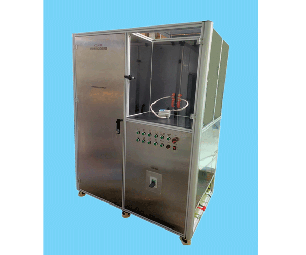
Safety considered during equipment design
Circuit breaker testing can involve electrical energy, and the risks vary with the test method. A safe arrangement should consider the required isolation, protection against accidental contact, connection security, emergency procedures, and the possibility of unexpected operation.
Where applicable, the equipment design may incorporate protective covers, clear terminal identification, suitable enclosures, interlocks, or emergency-stop functions. Whether these features are required and how they are implemented depends on the final equipment design and risk assessment.
We recommend that customers share the expected operating environment and applicable safety requirements during technical communication. The delivered equipment must be operated according to its instructions and the relevant workplace procedures. A test device does not remove the need for qualified personnel and proper electrical safety practices.
Performance verification before delivery
Before delivery, we carry out functional inspection and performance verification according to the agreed project requirements. This helps confirm that the equipment's main functions operate as intended and that the configured test workflow can be carried out.
Depending on the project, the inspection plan may include control operation, connection checks, test sequence execution, signal observation, data display, calculation functions, or report output. The actual verification items should be specified in the technical agreement.
We also distinguish between functional inspection and a formal measurement calibration. If a project requires traceable measurement results, specific calibration certificates, or a defined uncertainty statement, those requirements must be discussed and agreed upon. The documentation should reflect the work actually performed.
4. How to Select the Right Circuit Breaker Tripping Test Device
Start with the breaker type and rated values
The first selection factor is the type of breaker being tested. Low-voltage miniature circuit breakers, molded-case circuit breakers, air circuit breakers, residual-current devices, and high-voltage circuit breakers can have different test requirements. The applicable standard and test method may also vary according to the product category.
Rated voltage and rated current are important, but they do not fully describe the test requirement. The user also needs to identify the trip unit, protection functions, adjustment range, and intended test conditions. For electronic trip units, it may be necessary to know which functions can be tested through the available interface and which require a different test arrangement.
We recommend providing the manufacturer's datasheet and the exact model number whenever possible. These documents help determine whether the proposed Circuit Breaker Test Device is suitable and what additional information is needed.
Confirm the required test functions
Not every project needs the same set of tests. Some applications may focus on a specific trip function. Others may require several test points, time measurements, or a more complete inspection procedure.
Before requesting a quotation, prepare a list of the tests that must be performed. For each test, identify the input condition, expected response, measurement method, and acceptance criterion. If the procedure comes from a standard or a breaker manufacturer's instruction, provide the relevant document or clause reference where available.
This list helps us assess the required hardware, measurement channels, control functions, and software. It also helps establish the boundary between functions included in the quoted system and tests that require separate equipment.
Understand the difference between primary and secondary injection
One important selection question is whether the test method uses primary injection, secondary injection, or another procedure. These methods are not interchangeable.
Primary injection generally applies a test current through the main current path of the breaker or associated test arrangement. It can be used to evaluate aspects of the protection and trip chain under the conditions defined by the procedure. The required current, conductor arrangement, heating considerations, and test duration can make the setup more demanding.
Secondary injection generally applies suitable signals to the relevant inputs of an electronic trip unit or protection system. It can be useful for evaluating parts of the protection logic without driving the full primary current through the main circuit. However, it does not necessarily verify every part of the complete current path or switching operation.
The appropriate method depends on the breaker design, the test objective, and the applicable requirements. We therefore ask customers to confirm which method is required rather than assuming that one test device can perform both methods.
Define measurement and timing requirements
If the project requires trip-time measurement, the specification should state the required time range, measurement resolution, accuracy, and event definition. These are different parameters and should not be treated as synonyms.
Resolution describes the smallest displayed or recorded increment. Accuracy describes how close the measurement is expected to be to the relevant reference under defined conditions. Repeatability describes how consistent repeated results are when the same conditions and method are used. A high display resolution does not automatically mean high accuracy.
For example, a display that shows many decimal places may still be unsuitable if the input sensing, timing reference, or test arrangement does not support the required performance. The system should be evaluated as a complete measurement chain.
Check connection and interface compatibility
Connection compatibility affects both convenience and reliability. The breaker may require access to main terminals, auxiliary contacts, trip unit connections, control power, or a specific communication interface. These details should be reviewed before the test device is designed.
If several breaker models must be supported, the customer should identify whether the connections are similar or whether different adapters and fixtures are needed. Interchangeable accessories may be practical for some applications, while dedicated fixtures may be more suitable for repeated testing of one model.
Where software communication is required, the supported protocol and data fields should be confirmed. A general statement that a device supports automatic testing is not enough to establish compatibility with a particular breaker or production system.
Consider the daily workload and operating environment
A device used for occasional maintenance checks may need a different level of automation from equipment used to test many units during each production shift. The expected workload affects fixture design, setup time, operator interaction, data storage, and maintenance planning.
The operating environment also matters. The equipment may be installed in a laboratory, production area, repair workshop, or electrical test room. Available space, power supply, ventilation, ambient conditions, and access for maintenance can influence the design.
We discuss these practical issues before confirming the equipment structure. A solution that fits the actual workflow is generally more useful than one selected only by comparing a list of headline specifications.
Table 1. Comparison of common circuit breaker test approaches
The following table is a general engineering comparison intended to support equipment selection. It is not a performance report for a specific machine, and it does not mean that every Circuit Breaker Tripping Test Device supports every method.
| Test approach | Typical purpose | Main consideration | Important limitation |
|---|
| Primary injection testing | Applies a test current through a defined primary current path to evaluate specified protection behavior. | Required current, conductor arrangement, test duration, and thermal effects. | Requires a suitable high-current test arrangement and does not automatically cover every breaker test. |
| Secondary injection testing | Applies suitable signals to an electronic trip unit or protection input. | Compatibility with the trip unit, input signals, and defined test procedure. | May not verify the entire primary current path or every mechanical switching function. |
| Trip-time measurement | Measures a defined time interval associated with a trip response. | Clear start and stop events, suitable timing capability, and correct signal detection. | Results depend on the event definition and the measurement method. |
| Functional trip check | Checks whether a specified trip function responds under a defined condition. | Correct test condition, breaker settings, and acceptance criterion. | A functional check alone may not demonstrate full performance across all operating conditions. |
| Visual and mechanical inspection | Checks external condition, accessible mechanisms, markings, and specified mechanical functions. | Inspection criteria and manufacturer's instructions. | Does not replace electrical testing when electrical performance must be verified. |
Source and basis: This table summarizes general engineering distinctions between common testing approaches; it is not copied from a standard and does not specify the capabilities of our product. The appropriate method must be confirmed against the circuit breaker design, manufacturer's instructions, and applicable test requirements. For low-voltage circuit breakers, consult the scope of IEC 60947-2:2024. For specified high-voltage AC circuit breakers, consult IEC 62271-100:2021 with Amendment 1:2024.
Table 2. Technical information to confirm before ordering
| Item | Information to provide | Why it matters |
|---|
| Breaker category | Miniature, molded-case, air, residual-current, high-voltage, or another defined type. | Determines the relevant test method and equipment arrangement. |
| Rated values | Rated voltage, rated current, frequency, and other relevant nameplate data. | Helps establish the electrical requirements and compatibility limits. |
| Trip unit | Thermal-magnetic, electronic, residual-current, or another specified design. | Different protection principles require different test arrangements. |
| Required tests | Trip function, time measurement, setting verification, or other defined checks. | Defines the actual scope of the equipment. |
| Test method | Primary injection, secondary injection, or another specified procedure. | Affects the test source, connections, and measurement approach. |
| Measurement requirements | Required range, resolution, accuracy, and event definition where applicable. | Helps determine whether the measurement system is suitable. |
| Automation | Required automatic steps, operator actions, and model changeover process. | Helps match the system to the real workload. |
| Records | Required data fields, report format, storage, and export needs. | Defines the reporting and software scope. |
| Standards and acceptance | Applicable standard, manufacturer procedure, and pass/fail limits. | Provides the basis for evaluating the test results. |
Source and basis: The selection checklist is a practical project-planning tool. The scope of the applicable standard must be confirmed for the actual breaker category. Official references include IEC 60947-2:2024 for covered low-voltage circuit breakers and IEC 62271-100:2021+AMD1:2024 for covered high-voltage AC circuit breakers.
Table 3. Standards reference and application boundaries
Standards are useful when planning circuit breaker testing, but the applicable document depends on the equipment category and the specific test objective. The following references are included to help readers identify the correct starting point.
| Standard or guidance | Scope or purpose | Relevance to equipment planning |
|---|
| IEC 60947-2:2024 | Low-voltage switchgear and controlgear — Part 2: Circuit-breakers. Covers specified circuit breakers with rated voltage not exceeding 1,000 V AC or 1,500 V DC, subject to the standard's stated scope. | Relevant when the breaker falls within the scope of this low-voltage standard. The specific test clauses must be reviewed for the intended application. |
| IEC 62271-100:2021+AMD1:2024 | High-voltage switchgear and controlgear — Part 100: Alternating-current circuit-breakers. Applies to specified three-phase AC circuit breakers designed for indoor or outdoor installation and systems above 1,000 V. | Relevant to the covered high-voltage AC breaker category and its specified making-breaking tests. It is not a universal standard for all breaker tests. |
| NIST metrological traceability guidance | Explains that measurement traceability requires a documented chain of calibrations or comparisons, with measurement uncertainty considered at each relevant link. | Useful when defining measurement documentation, reference equipment, and traceability claims for test results. |
Official sources: IEC 60947-2:2024, IEC 62271-100:2021+AMD1:2024, and the NIST guidance on metrological traceability.
These references should not be interpreted as a declaration that a particular machine complies with every listed standard. The applicable test clauses, test setup, measurement requirements, and acceptance criteria must be confirmed for the specific breaker and project. Where a customer requires formal conformity assessment, the relevant product requirements and test documentation should be agreed before the equipment is built.
5. Application Industries and Typical Use Cases
Electrical equipment manufacturing
Circuit breaker manufacturers need to control product quality throughout production. Depending on the product and the manufacturer's quality plan, testing may be carried out at different stages, including component inspection, assembly checks, functional verification, and final inspection.
A suitable Circuit Breaker Tripping Test Device can support a defined inspection procedure for the breaker types it is designed to handle. When testing is repeated across a production batch, a consistent setup helps the quality team compare results and identify unusual readings that require further investigation.
Manufacturers should determine which tests are required at each stage and avoid treating a single trip test as proof of every product requirement. The equipment should be selected according to the specific tests that must be performed and recorded.
Switchgear and controlgear production
Switchgear assemblies use protective and switching devices to control electrical distribution. Depending on the assembly, circuit breakers may be installed with auxiliary contacts, trip circuits, control wiring, or other components that influence the overall operating sequence.
Testing may therefore need to consider the breaker itself as well as the relevant interface with the assembly. The correct test arrangement depends on whether the objective is to evaluate the breaker trip mechanism, a trip unit, a control circuit, or a wider system function.
We recommend clarifying the boundary of the test. If the customer needs to evaluate only a standalone breaker, the fixture and connections may be simpler. If the test includes a complete switchgear assembly, the electrical interface and safety requirements may be more involved.
Electrical laboratories and inspection institutions
Testing laboratories and inspection institutions often require defined methods, suitable measurement equipment, controlled conditions, and records that can be reviewed later. A circuit breaker tripping test may form one part of a wider evaluation program.
For these applications, the test procedure should identify the input condition, measurement method, required test points, acceptance limits, and the information to be recorded. If measurement results must be traceable to specified references, the laboratory should define the necessary calibration arrangements and uncertainty requirements.
We can discuss customized equipment configurations according to the intended laboratory workflow. However, the use of a test device alone does not establish laboratory accreditation or guarantee that every result is suitable for a formal conformity decision. Those matters depend on the complete quality system, personnel competence, methods, and relevant accreditation requirements.
Electrical maintenance and repair services
Maintenance teams may need to investigate breaker behavior after an electrical fault, after repair, or during scheduled inspection. Testing can help determine whether a defined tripping function responds as expected under the specified conditions.
The test method must be selected carefully. A breaker that appears to operate normally during a simple functional check may still require additional testing if the maintenance procedure calls for it. Likewise, a test result outside the expected range should be investigated rather than treated as proof of a single cause.
For maintenance applications, practical considerations include ease of connection, clear operating instructions, safe handling, and compatibility with the breaker models encountered by the service team. A dedicated test device can be useful when the same type of inspection is performed regularly.
Industrial plants and electrical distribution systems
Factories, commercial facilities, and infrastructure operators rely on circuit breakers to protect distribution circuits and connected equipment. Maintenance procedures may include inspection, functional checks, and more specific tests based on the equipment type and service conditions.
A suitable test system can support these activities when the method and configuration match the breaker. Before selecting equipment, the responsible team should determine whether the required work involves a low-voltage breaker, a high-voltage breaker, an electronic trip unit, or a broader protection system.
It is also important to consider the operating environment and safety procedures. Testing should be performed by qualified personnel using the required isolation, protective equipment, and approved work instructions. Equipment selection should support the site's maintenance process rather than replace it.
Research, development, and product verification
Engineering teams may need to evaluate a new breaker design, compare trip behavior across prototype units, or investigate the effect of different settings. In these cases, the test setup may need to support a defined range of test conditions and record results in a format suitable for analysis.
Development work can involve requirements that are not covered by a standard production fixture. These may include special connections, different control inputs, additional measurement channels, or a customized data format. Such requirements should be documented early because they can affect hardware design, software, and verification procedures.
At Guangzhou Chuangge Automation Equipment Co., Ltd., we work with customers to clarify these project-specific needs and determine which functions should be included in the final equipment.
6. Our Customization, Manufacturing, and Quality Verification Process
Requirement collection and feasibility review
We begin each customized equipment project by collecting the technical information needed to define the test task. For a Circuit Breaker Tripping Test Device, this normally includes the breaker type, model, rated values, trip unit, required test functions, applicable procedure, and expected results.
We may also request technical drawings, wiring diagrams, product manuals, sample units, and information about the existing inspection workflow. These materials help us understand how the breaker must be connected and which measurements are required.
At this stage, we discuss what the equipment must do and what falls outside the project scope. If a customer requires primary injection, secondary injection, trip-time measurement, data storage, or a particular report format, these requirements should be identified clearly rather than left to assumption.
We also review practical conditions such as installation space, power supply, expected test frequency, operator experience, and transport requirements. These details can influence the mechanical structure and control design.
Mechanical and electrical design
Once the technical scope is clear, the design process considers the structure, fixtures, electrical connections, test source or interface, control system, and any required software. Each part must be appropriate for the intended breaker and test procedure.
The mechanical structure may include a support frame, a mounting fixture, an access panel, protective covers, or model-specific adapters. The electrical design may involve the required test connections, control components, signal inputs, and protective arrangements. Where data acquisition is needed, the design must also account for compatible measurement signals and data handling.
We do not assume that every project needs the same hardware or software. The configuration should reflect the required tests, supported breaker models, operating environment, and acceptance criteria. A clear specification helps avoid adding unnecessary functions while ensuring that important requirements are not overlooked.
Component preparation and equipment assembly
After the design is confirmed, the required components and structural parts are prepared for assembly. Depending on the project, this may involve machining, fabrication, electrical installation, wiring, control integration, and software configuration.
During assembly, attention should be given to connection security, component positioning, cable routing, labeling, access for inspection, and the clarity of the operating interface. These details can make a real difference to day-to-day operation and maintenance.
For equipment intended to support more than one breaker model, interchangeable fixtures or connection accessories may be considered. Their suitability depends on the differences between the models and the frequency of changeover. If one breaker model accounts for most of the workload, a dedicated fixture may be the more practical option.
Functional inspection and performance verification
Before delivery, we carry out functional inspection and performance verification according to the agreed project scope. The purpose is to check that the delivered equipment performs its specified functions and that the configured test workflow can be carried out.
Depending on the configuration, verification may include control operation, connection checks, sequence execution, signal detection, timing functions, data display, calculation logic, and report output. The actual items should be agreed upon before production so that the customer understands how acceptance will be evaluated.
If a project requires measurement performance to be demonstrated, the acceptance plan should identify the reference equipment, test conditions, measurement points, and evaluation criteria. Functional inspection is not automatically the same as a formal calibration, and the documents supplied should reflect the tests actually completed.
We recommend agreeing on these details before the machine is built. A clear acceptance plan makes it easier to confirm whether the delivered system meets the project's defined requirements.
Operating instructions and technical documentation
Operating instructions and technical documentation are provided as agreed. Depending on the project, the documents may cover equipment identification, the operating sequence, connection requirements, safety precautions, routine checks, and basic maintenance information.
For customized equipment, the documentation should reflect the actual configuration. If the machine supports several breaker models or test procedures, the relevant operating steps and limitations should be described clearly.
Good documentation helps operators follow the intended procedure and helps maintenance staff understand the equipment during routine inspection. If the customer requires a specific report template, test record, or additional document, it should be identified during the technical and commercial review.
Production cycle and project schedule
Our typical production cycle for customized testing equipment is approximately 30 to 60 days, depending on the specifications and customization requirements. This is a general planning range, not a guaranteed delivery date for every project.
A project with a clear specification and straightforward fixture requirements may be easier to schedule than one involving a new test source, complex electrical integration, specialized software, or several rounds of design review. Component availability and changes after design approval can also affect the schedule.
We therefore recommend confirming the breaker types, test functions, measurement requirements, acceptance criteria, documentation, and shipping arrangements before production begins. This gives both sides a clearer basis for planning and reduces the chance of avoidable delays.
Packing and transportation
After the agreed inspection and documentation steps are complete, the equipment is prepared for shipment. Depending on its dimensions, weight, structure, and destination, protective materials and sturdy wooden cases can be used to help reduce the risk of damage during handling and transport.
We can discuss sea, air, or land transportation according to the destination, schedule, and shipping requirements. The final arrangement should take account of the equipment's packaging dimensions, loading conditions, and any special handling needs.
Payment terms are negotiable and should be confirmed in the commercial agreement. The quotation should also clarify the agreed equipment configuration, inspection scope, documentation, delivery schedule, packing method, and transport arrangements.
7. Why Choose Guangzhou Chuangge Automation Equipment Co., Ltd.?
Experience in customized testing equipment
At Guangzhou Chuangge Automation Equipment Co., Ltd., our work focuses on customized testing equipment for different industrial requirements. Our product applications cover construction materials and components, wires and cables, plastics and textiles, electrical plugs, sockets and switches, electronic products, and home appliances.
These sectors have different testing objectives, product structures, and technical requirements. Our experience in equipment customization encourages us to begin with the test method and required result rather than assume that a standard machine configuration will suit every project.
For circuit breaker tripping test equipment, this means reviewing the breaker type, protection function, connection requirements, and acceptance criteria before defining the design. Our aim is to develop a solution that fits the customer's real inspection process.
A standards-aware approach to equipment design
Testing standards help define how a product should be evaluated, but the scope of each standard must be understood. IEC 60947-2 covers specified low-voltage circuit breakers, while IEC 62271-100 addresses specified high-voltage alternating-current circuit breakers. These documents should not be treated as interchangeable or as universal standards for every electrical switching device.
We encourage customers to identify the relevant standard, manufacturer's procedure, or internal quality specification during the initial technical discussion. Where the applicable requirement is unclear, it should be confirmed by the responsible engineering or quality team before the test equipment is finalized.
This approach helps reduce misunderstandings about the intended test functions and gives the project a clearer technical foundation. It also helps ensure that the final acceptance procedure is linked to the actual application rather than a general product description.
Certified management systems
Our company has obtained ISO 9001 Quality Management System, ISO 14001 Environmental Management System, and ISO 45001 Occupational Health and Safety Management System certifications. These certifications relate to management systems and should not be interpreted as product-specific certification of every testing device.
For an equipment project, product performance must be assessed against the agreed technical specification and the relevant acceptance procedure. Where customers require specific product certificates, measurement records, or conformity documentation, those requirements should be discussed separately and confirmed in writing.
Intellectual property and technical development
Our company has a portfolio of more than 20 patents, including invention patents, utility model patents, and software patents. This portfolio reflects our wider technical development work. The relevance of a particular patent to a specific product should be established from the applicable patent information rather than assumed from the overall portfolio.
For customized testing equipment, technical development is most useful when it solves a defined testing problem. This may involve improving the test workflow, developing a suitable fixture, organizing control functions, or creating a practical method of recording results. The appropriate solution depends on the customer's application and the agreed design requirements.
Clear project communication
Customized equipment involves several decisions that affect one another. The test method influences the electrical design; the breaker type influences the fixture and connection arrangement; the measurement requirements influence the instruments and data handling; and the acceptance criteria influence the verification plan.
We therefore encourage customers to provide detailed technical information as early as possible. When requirements are incomplete, we clarify the missing points before confirming the design. This helps both sides establish a realistic scope, schedule, and acceptance procedure.
We also discuss production timing, payment terms, technical documentation, packing, and transportation as part of the project. These commercial and delivery details are confirmed according to the final agreement.
A practical solution for the intended workload
Not every customer needs a highly automated system with a large number of functions. Some need a dedicated test arrangement for one breaker model. Others need to support several models, record results digitally, or integrate the equipment into a production inspection process.
We focus on identifying which functions are necessary for the defined task. This helps avoid a mismatch between the equipment and the customer's daily work. A good solution should be technically appropriate, straightforward to operate, and supported by a clear specification.
8. Frequently Asked Questions About Circuit Breaker Tripping Test Devices
Q1. What is a Circuit Breaker Tripping Test Device used for?
It is used to support the evaluation of defined circuit breaker tripping functions under specified test conditions. Depending on the equipment configuration, it may support controlled test inputs, observation of trip response, timing measurements, result evaluation, and data recording. The actual functions depend on the breaker type and the agreed technical specification.
Q2. Can one test device work with every circuit breaker?
No single configuration should be assumed to support every breaker type. Low-voltage miniature breakers, molded-case breakers, air circuit breakers, residual-current devices, and high-voltage breakers may require different test methods and connections. Compatibility should be confirmed using the breaker model, technical datasheet, rated values, trip unit information, and applicable procedure.
Q3. Can the device test both low-voltage and high-voltage circuit breakers?
That cannot be assumed without reviewing the design. Low-voltage and high-voltage breakers have different construction, ratings, test methods, and safety requirements. A system intended for one category may not be suitable for the other. If both categories are required, the project should identify the relevant breaker models and tests so that the necessary configurations can be evaluated separately.
Q4. Does a tripping test measure operating time?
It may, if timing measurement is included in the selected configuration and required by the test procedure. The specification should define the measurement range, required accuracy, and the start and stop events. Not every functional trip test requires a timing measurement, and not every test device includes timing functions.
Q5. What is the difference between primary injection and secondary injection testing?
Primary injection applies a test current through a defined primary current path, while secondary injection applies suitable signals to an electronic trip unit or protection input. They evaluate different parts of the system and are not interchangeable. The correct method depends on the breaker design, test objective, and applicable procedure.
Q6. Can the equipment automatically judge pass or fail?
Automatic evaluation may be included if the software is configured to compare the test result with the appropriate acceptance limits. The limits must be correct for the breaker model and test procedure. Automatic pass/fail output does not replace the need to validate the procedure, settings, measurement method, and acceptance criteria.
Q7. Can the device store and export test data?
Data storage and export can be discussed during customization. Depending on the confirmed configuration, the system may record breaker identification, test conditions, measured values, results, and other agreed fields. The required report structure, file format, and interface should be specified before production.
Q8. Which standards does the device follow?
The applicable standard depends on the circuit breaker category and the test being performed. IEC 60947-2:2024 covers specified low-voltage circuit breakers, while IEC 62271-100:2021 with Amendment 1:2024 applies to specified high-voltage AC circuit breakers. The relevant clauses and test requirements must be reviewed for the actual application. A general product name does not establish compliance with a standard.
Q9. What information is needed for a quotation?
Please provide the breaker manufacturer and model, rated voltage and current, trip unit type, required test functions, test method, required measurement range and accuracy, applicable standards or procedures, and reporting requirements. Drawings, wiring diagrams, product manuals, and sample units can help us evaluate fixture and connection requirements. If you have an existing inspection procedure, sharing it will make the technical discussion more efficient.
Q10. What is the typical production lead time?
The typical production cycle for customized testing equipment is approximately 30 to 60 days. The actual lead time depends on the design complexity, component availability, fixture requirements, software scope, and technical confirmation process. A project-specific schedule can be discussed once the configuration has been reviewed and agreed.
Q11. What inspection is performed before delivery?
Functional inspection and performance verification are carried out according to the agreed project scope. Depending on the configuration, the checks may cover control functions, connections, test sequence operation, measurement functions, data display, calculations, or report output. Any specific acceptance tests should be documented in the technical agreement before production begins.
Q12. Does the device include calibration certificates?
The documents supplied depend on the agreed project scope. If the customer requires calibration certificates for measurement instruments, traceability documentation, or a specified uncertainty statement, these requirements should be confirmed before ordering. A functional inspection report and a formal calibration certificate are not necessarily the same document.
Q13. Can the device be customized for our own breaker model?
Customization can be discussed based on the breaker model and test requirements. Please provide technical drawings, datasheets, wiring information, the required test procedure, and the expected result format. We can then review the fixture, connection arrangement, measurement requirements, and control functions before confirming a design.
Q14. How is the equipment packed and shipped?
We can arrange sea, air, or land transportation according to the destination and delivery requirements. Protective materials and sturdy wooden cases can be used to help protect the equipment during handling and transport. The final packing method depends on the machine's dimensions, weight, structure, and shipping route.
Q15. Are payment terms negotiable?
Yes. Payment terms are negotiable and should be confirmed in the commercial agreement before the order is finalized. The agreement should also identify the equipment configuration, inspection scope, documentation, production schedule, packing, and delivery arrangements.
Request a Customized Circuit Breaker Tripping Test Device
Selecting the right Circuit Breaker Tripping Test Device begins with a clear definition of the test objective. The breaker type, rated values, trip unit, required test method, measurement requirements, and acceptance criteria all influence the final equipment design. When these details are established early, it becomes easier to determine which functions are necessary and how the equipment should be verified before delivery.
At Guangzhou Chuangge Automation Equipment Co., Ltd., we develop customized testing equipment based on customer requirements and the relevant technical procedures. We discuss the intended application, connection arrangement, required automation, result recording, and acceptance plan before confirming the equipment configuration.
If you are looking for Circuit Breaker Tripping Test Equipment for electrical manufacturing, laboratory testing, maintenance, or quality inspection, we welcome your inquiry. Please share the breaker model, technical datasheet, required test functions, applicable standards, and desired report format. Our team can review the information with you and discuss a suitable customized solution.
Contact Guangzhou Chuangge Automation Equipment Co., Ltd. to discuss your circuit breaker testing requirements and request a project-specific quotation.
Technical References
Technical note: The standards above are reference sources for identifying relevant requirements. Their applicability depends on the breaker category and intended test. The functions, supported models, measurement performance, and acceptance criteria of a specific Circuit Breaker Tripping Test Device must be confirmed in its project-specific technical specification.


