<span style="font-size: 16px;">Fully Automatic <a href='https://int.cgtesting.cn/tag/liquid-level-gauge-calibration-device' target='_blank' class='key-tag'><font><strong>Liquid Level Gauge Calibration Device</strong></font></a> for Industrial Measurement</span>Fully Automatic Liquid Level Gauge Calibration Device for Reliable Measurement Verification
When a liquid level gauge gives an incorrect reading, the problem is not always obvious. A tank may appear to contain enough liquid when the actual level is lower, or an automated system may receive a signal that does not match the real liquid level. In industrial production, these differences can affect process control, product quality, equipment operation, and routine maintenance. That is why checking the performance of a liquid level measuring instrument is an important part of a reliable measurement system.
At Guangzhou Chuangge Automation Equipment Co., Ltd., we focus on the customization of testing equipment for different industries and technical requirements. With our experience in testing equipment development and our understanding of relevant standards, we work with customers to turn their measurement and inspection needs into practical equipment solutions. Our approach is not simply to supply a machine with a familiar name. We first need to understand what the customer measures, how the instrument works, and what the final test results must demonstrate.
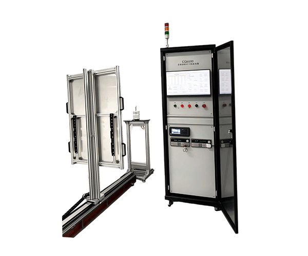
Our Fully Automatic Liquid Level Gauge Calibration Device is intended for applications that require a structured and repeatable method of checking liquid level gauges. Depending on the instrument type and the agreed configuration, a system of this kind may be designed to support reference-level comparison, automatic test sequencing, data recording, result analysis, and the preparation of calibration records. The exact functions depend on the selected configuration and should be confirmed against the customer's technical specification before an order is placed.
For manufacturers, inspection departments, laboratories, and industrial users, automation can make calibration work more consistent and easier to manage. Instead of relying entirely on manual operation, an appropriately configured automatic calibration system can help operators follow a defined procedure, reduce repetitive handling, and organize measurement results in a more systematic way.
We develop customized testing equipment based on the actual application rather than assuming that every customer needs the same setup. Before recommending a solution, we discuss the gauge type, measurement range, required test points, reference method, operating environment, data requirements, and applicable technical documents. This early discussion helps us determine whether a standard configuration is suitable or whether a more specialized arrangement is needed.
1. What Is a Fully Automatic Liquid Level Gauge Calibration Device?
Understanding the purpose of liquid level gauge calibration
A liquid level gauge is an instrument used to indicate or measure the level of liquid in a container, tank, vessel, or other system. Depending on its design, it may provide a direct visual reading, an electrical output, a digital value, or a signal that can be sent to a control system. Liquid level instruments are used in water treatment, chemical processing, industrial storage, equipment manufacturing, research facilities, and many other applications.
However, an instrument's displayed value may differ from the reference value. The difference may come from sensor characteristics, installation conditions, mechanical wear, changes in the measuring element, electrical signal processing, environmental influences, or other factors. Calibration provides a structured way to compare the instrument's indication with an appropriate reference under defined conditions.
In simple terms, the operator checks what the gauge indicates at a known reference point. The difference between the indicated value and the reference value can then be evaluated. Repeating this process at several points across the intended measurement range helps build a clearer picture of the instrument's performance.
For example, imagine that a liquid level gauge is expected to indicate a reference level of 200 mm. If the gauge displays 203 mm under the specified test conditions, the indication error is +3 mm. Whether this difference is acceptable depends on the instrument's specification, the applicable test procedure, the uncertainty of the reference measurement, and the acceptance criteria agreed upon for the application.
This is an important distinction: calibration does not automatically mean that an instrument passes or fails. Calibration establishes the relationship between the instrument's indication and a reference value. A conformity decision requires a defined tolerance or acceptance rule against which the results can be compared.
What does "fully automatic" mean?
The term "fully automatic" describes the intended level of automation in the calibration process, but it should not be treated as a universal technical specification. Different liquid level gauges require different reference methods, fixtures, test conditions, and control arrangements. The automation level must therefore be confirmed for the actual machine configuration.
Depending on the project requirements, an automatic liquid level gauge calibration system may coordinate the test sequence, control a reference-level mechanism, collect readings from compatible instruments, calculate differences, store results, and display a report. Certain applications may require manual installation, connection, zeroing, or confirmation by an operator even when the measurement sequence itself is automated.
We discuss these details before designing the equipment. A gauge with a digital communication interface may be handled differently from a gauge that provides an analog signal. A mechanical float-type instrument may need a different fixture from a non-contact ultrasonic or radar level instrument. A system designed for one measurement principle should not be assumed to support every other principle without suitable engineering changes.
Typical applications of the device
A Fully Automatic Liquid Level Gauge Calibration Device can be developed for applications such as:
Checking the indication performance of compatible liquid level gauges.
Comparing instrument readings with a defined reference level.
Evaluating indication error at selected test points.
Repeating measurement checks under controlled conditions.
Recording test readings for quality inspection and traceability.
Supporting production inspection and instrument maintenance workflows.
Helping laboratories organize repeatable calibration procedures.
Creating a documented basis for instrument adjustment or further investigation.
These are potential application functions, not a claim that every function is included in every machine. The final configuration should be matched to the gauge model, measurement principle, range, interface, and requested procedure. This is the most practical way to avoid buying a system that looks suitable on paper but does not fit the instruments used in the customer's actual workflow.
2. Working Principle: How Does an Automatic Liquid Level Gauge Calibration System Work?
Step 1: Identify the instrument and define the calibration procedure
Before calibration begins, the instrument must be identified. We recommend recording the gauge model, serial number if applicable, measuring range, display or output type, and the manufacturer's stated specifications. The operator should also confirm whether the gauge measures liquid level directly or calculates the level from another physical quantity.
This matters because the same displayed unit does not necessarily mean that two instruments use the same measurement principle. A float-operated gauge, for instance, may respond to the movement of a mechanical element. An ultrasonic gauge estimates distance from a transmitted and returned sound signal. A radar gauge uses electromagnetic waves. A hydrostatic level instrument may derive liquid level from pressure, based on the relevant liquid properties and installation conditions.
These instruments may all be used to determine liquid level, but their calibration arrangements can be quite different. For that reason, we first establish what the customer needs to verify and then select a suitable reference method and fixture.
Step 2: Establish a suitable reference value
Calibration depends on having a reference value that is appropriate for the quantity being measured. The reference method could involve a known physical level, a reference displacement, a controlled test arrangement, or another method suitable for the instrument under test. The correct choice depends on the gauge's operating principle and the procedure used.
For a gauge that can be compared directly with a physical liquid level, the test setup may use a controlled liquid column or a suitable reference arrangement. For a non-contact instrument, the setup may need a defined target distance and an arrangement that reflects the intended measurement conditions. For an instrument that calculates liquid level from pressure, the procedure may need to consider the relationship between pressure, liquid density, and height.
We do not treat these methods as interchangeable. A reference method that is appropriate for one type of instrument may not be suitable for another. The calibration plan should describe the reference, the measurement points, the test conditions, and the way the instrument's indication will be recorded.
Step 3: Install and connect the gauge
The instrument is installed in the fixture or test position specified for the calibration procedure. Mechanical stability, alignment, electrical connections, and the position of the sensing element can all influence the results. If the gauge requires a particular mounting orientation, that condition should be followed.
Where an electrical or digital connection is required, the interface should be confirmed before the system is built. Depending on the instrument, this may involve analog signals, switching outputs, serial communication, or a manufacturer-specific interface. Not every gauge provides a compatible electronic output, so data acquisition functions must be selected accordingly.
Our engineering discussions cover these practical details because they influence both the design and the ease of use. A calibration device should not only carry out the intended measurement. It should also allow the operator to install the instrument safely and repeat the procedure without unnecessary adjustments.
Step 4: Carry out measurements at defined test points
Once the instrument is installed and the test conditions are stable, the calibration sequence can begin. The reference value and the gauge indication are recorded at each selected point. The number and location of test points depend on the applicable procedure and the intended use of the instrument.
For example, a calibration procedure might include points near the lower, middle, and upper portions of the measuring range. More points may be needed when the application requires a detailed evaluation of performance across the range. The points should be selected according to the relevant specification rather than chosen simply because they are convenient for the operator.
In an automated configuration, the system may guide or execute the defined sequence, collect compatible instrument readings, and associate each result with its corresponding reference value. Where the system requires operator confirmation or manual input, the workflow should make that requirement clear.
Step 5: Calculate indication error and review the results
A common calculation is the indication error, which is the instrument's indicated value minus the reference value. For example, if the reference value is 500 mm and the instrument indicates 496 mm, the indication error is -4 mm.
The calculation is straightforward, but interpreting the result requires care. The operator must know the units, sign convention, specified tolerance, measurement conditions, and relevant uncertainty. A difference of a few millimeters may be acceptable for one application but unacceptable for another. The acceptable error cannot be determined from the displayed value alone.
Where configured, calibration software can calculate errors automatically, display the results, and organize them into a report. Automatic calculation can reduce arithmetic mistakes and make records easier to review. It does not, however, remove the need for a correct test method, a suitable reference, and a clear acceptance criterion.
Step 6: Save the record and determine the next action
After the measurements have been completed, the results can be reviewed against the specified requirements. Depending on the agreed configuration, the system may store measurement values, calculate errors, identify results outside defined limits, or export records for quality management.
If a reading falls outside the allowed tolerance, the next step depends on the customer's procedure. The instrument may need adjustment, maintenance, further investigation, or a repeat calibration after the cause has been identified. The calibration device should provide reliable evidence of what was measured; it should not replace engineering judgment about why a result is outside the expected range.
For us, a useful calibration system is one that makes this complete process easier to control, from instrument identification to the final record. Automation is most valuable when it improves repeatability, reduces unnecessary manual work, and helps the user understand the results.
3. Main Features and Technical Advantages
Automated test sequences for repeatable operation
Manual calibration often involves repeating the same actions at multiple test points. Depending on the instrument and the procedure, operators may need to adjust a reference condition, wait for the reading to stabilize, record values, calculate errors, and prepare documentation. Repeating these steps for many instruments can take time and introduce avoidable differences in how the work is performed.
An automatic calibration device can help organize these steps into a defined sequence. Where the selected configuration supports automated control and data acquisition, the system can guide or carry out repetitive operations in a consistent order. This makes it easier to apply the same procedure to multiple instruments and to identify deviations in the workflow.
Automation does not guarantee a particular level of accuracy by itself. The final result still depends on the reference equipment, mechanical setup, environmental conditions, instrument compatibility, software logic, and the calibration procedure. We therefore consider automation as one part of a complete measurement solution, rather than a substitute for sound measurement practice.
Reference-based measurement and error evaluation
The purpose of calibration is to establish the relationship between the instrument's indication and an appropriate reference. A well-designed calibration workflow keeps these two values clearly linked. This helps users understand not only what the gauge displayed, but also how that indication compared with the reference at each test point.
Depending on the required functions, the system can be configured to record reference values and instrument readings together. It may also calculate indication errors using a defined formula and display the results in a structured format. The precise calculation and reporting functions should be confirmed in the technical specification.
We encourage customers to define the required measurement range, test points, acceptable error, and data format early in the project. Doing so makes it easier to select the appropriate reference method and prevents unnecessary functions from increasing equipment complexity.
Data recording and traceable documentation
Calibration records are important when an organization needs to compare instrument performance over time, investigate a quality issue, or demonstrate that a defined procedure has been followed. If values are written down manually and later transferred into another system, there may be opportunities for transcription mistakes, missing fields, or inconsistent naming.
Where the chosen configuration includes data acquisition and reporting functions, the calibration device can help organize readings and associate them with instrument identifiers and test conditions. The customer should define which fields are needed, such as instrument model, serial number, test date, reference values, measured indications, calculated errors, and operator information.
It is also important to distinguish between recording results and proving metrological traceability. A digital report does not automatically establish traceability. Traceability requires a documented chain of appropriate calibrations or comparisons to specified references, with measurement uncertainty considered at the relevant stages. The National Institute of Standards and Technology explains these principles in its guidance on metrological traceability.
For more information, see the [NIST guidance on metrological traceability](https://www.nist.gov/metrology/metrological-traceability). We recommend that customers define any traceability or certificate requirements with their quality team or calibration laboratory before finalizing the equipment specification.
Customized fixtures and instrument compatibility
One of the most important design questions is how the gauge will be held, connected, and measured. Different instruments may vary in body dimensions, mounting arrangements, sensing positions, connection types, and measurement ranges. A fixture that fits one gauge may not hold another gauge securely or position its sensing element correctly.
We therefore discuss the actual instruments that will be tested. Drawings, photographs, model numbers, technical manuals, and sample units can all help clarify the requirements. Based on the agreed scope, the mechanical fixture, connection arrangement, test sequence, and data interface can be considered together.
Customization should solve a real operational problem. If a customer tests only one gauge model, a dedicated fixture may be the simplest solution. If several models must be supported, an adjustable or interchangeable fixture may be more suitable. The right choice depends on changeover frequency, instrument dimensions, positioning requirements, and the expected workload.
A user-oriented operating workflow
Calibration equipment is often used by technicians who need a clear and repeatable procedure rather than a complicated interface. A practical system should make the test sequence understandable, identify the required inputs, and present the results in a way that helps the operator recognize the next step.
During customization, we consider how the equipment will be used in everyday work. Questions include whether the operator needs to select an instrument model, enter identification information, choose a test procedure, review measurement values, or export a record. The answers help determine what the control interface and software should do.
We avoid assuming that a more complicated interface is always better. A focused interface with the right functions can be easier to learn and maintain than a system filled with options the customer rarely uses.
Key technical items to confirm before ordering
Because the final design depends on the target instrument, we recommend confirming the following items during technical communication:
Instrument type: mechanical, ultrasonic, radar, hydrostatic, capacitive, or another measurement principle.
Measurement range: the minimum and maximum values the system must support.
Reference method: how the reference value will be established and verified.
Test points: the number and location of required measurement points.
Accuracy requirements: the permitted indication error and the reference measurement capability needed for the application.
Interface: the electrical or digital connection, if instrument readings are to be collected automatically.
Automation level: which operations should be automatic and which require operator confirmation.
Software and reports: the required calculations, storage fields, export formats, and record structure.
Operating environment: temperature, humidity, installation space, power supply, and other relevant conditions.
Applicable procedure: the customer specification, manufacturer instructions, or relevant standard to be followed.
These details are more useful than relying on a general product label alone. They help both sides establish a realistic scope and make sure that the proposed equipment addresses the actual measurement task.
4. Comparison Tables: Choosing the Right Calibration Approach
Table 1. Manual checks compared with an automated calibration workflow
The following table is a practical comparison of typical workflow differences. It is not a performance test of a specific machine, and it does not promise a particular time saving or accuracy improvement. Actual results depend on the instrument, test method, operator, and equipment configuration.
| Comparison item | Manual calibration workflow | Automated calibration workflow |
|---|
| Test sequence | The operator carries out each step according to the procedure. | Configured steps may be guided or executed automatically. |
| Reading collection | Values may be read and entered manually. | Compatible instruments may provide readings directly to the system. |
| Error calculation | May require manual calculation or a separate spreadsheet. | Software may calculate error automatically when configured. |
| Record organization | Records may be stored on paper or entered into a separate system. | Configured software may organize results in digital records. |
| Operator involvement | Often requires repeated hands-on actions throughout the procedure. | Some repetitive actions may be reduced, while installation and verification may remain manual. |
| Instrument compatibility | Can be adapted by the operator, subject to the available reference equipment and method. | Depends on fixtures, interfaces, software, and the supported calibration procedure. |
| Best fit | Occasional checks, simple setups, or tasks where automation is not justified. | Repeated testing, standardized workflows, or applications that benefit from structured data handling. |
Source and basis: This is an engineering workflow comparison prepared for product selection, not a quotation from a standard or a third-party performance study. For the underlying principles of calibration records and traceability, consult [NIST's metrological traceability guidance](https://www.nist.gov/metrology/metrological-traceability). The specific functions of an automatic system must be verified against its approved technical specification.
Table 2. Important factors when selecting a liquid level gauge calibration device
Different applications place different demands on a calibration setup. The table below can be used as a starting point when preparing a request for quotation or technical specification.
| Selection factor | Questions to answer | Why it matters |
|---|
| Gauge measurement principle | Does the instrument use a float, ultrasonic sensing, radar, pressure, capacitance, or another method? | The principle affects the reference method, fixture, and measurement procedure. |
| Measurement range | What are the required lower and upper limits? | The reference arrangement must cover the intended range. |
| Required test points | How many points are needed, and where are they located? | Test points determine the calibration sequence and workload. |
| Permitted error | What tolerance or acceptance criterion applies? | The reference system and uncertainty must be appropriate for the decision being made. |
| Instrument interface | Is the indication visual, analog, digital, or available through a communication protocol? | Automatic reading collection requires a compatible method. |
| Data and reporting | Which identification fields, results, and export formats are required? | Early planning reduces later software changes. |
| Daily workload | How many instruments are tested per shift or day? | Workload helps determine whether a dedicated fixture or more automation is worthwhile. |
| Applicable requirements | Which customer procedures, manufacturer instructions, or standards apply? | The equipment and method must be suitable for the actual compliance objective. |
Source and basis: The selection factors above are practical engineering considerations. The importance of defining the measurand, reference standards, calibration procedure, and uncertainty is consistent with [NIST's guidance on metrological traceability](https://www.nist.gov/metrology/metrological-traceability). The final requirements must be established for the specific gauge and application.
Table 3. Relevant standards and guidance: scope and limitations
A common mistake when purchasing calibration equipment is to assume that one general standard covers every kind of level instrument. In practice, standards have specific scopes. The references below illustrate how to check the relevance of a standard before applying it to a project. They are not a declaration that all of them apply to every liquid level gauge calibration device.
| Reference | Published scope or purpose | How to use it when planning a project |
|---|
| ISO 4064-1:2024 | Metrological and technical requirements for meters measuring cold potable water and hot water flowing through fully charged, closed conduits. | Relevant when the instrument is a water meter within the standard's scope. It should not automatically be applied to tank level gauges. |
| ISO 4064-2:2024 | Test methods for type evaluation and initial verification of water meters within the relevant ISO 4064 scope. | Useful when planning testing for applicable water meters; confirm the instrument category and the intended conformity procedure first. |
| NIST metrological traceability guidance | Explains documented calibration chains, reference standards, and the role of measurement uncertainty. | Useful for developing a documented calibration process and assessing whether the reference chain supports the intended measurement claim. |
Official sources: [ISO 4064-1:2024](https://www.iso.org/standard/80868.html), [ISO 4064-2:2024](https://www.iso.org/standard/80869.html), and [NIST Metrological Traceability](https://www.nist.gov/metrology/metrological-traceability).
The important point is that water flow meters and liquid level gauges are not the same category of instrument. ISO 4064 addresses water meters within its defined scope; it should not be presented as a universal calibration standard for all liquid level measuring devices. Before finalizing a calibration system, we recommend confirming the applicable standards, national or regional rules, and instrument manufacturer's requirements with the responsible technical or quality team.
5. Application Industries and Typical Use Cases
Water treatment and water management
Water treatment facilities use level instruments to monitor tanks, reservoirs, treatment vessels, and other process equipment. A level indication can help operators understand whether a container is filling, emptying, or approaching a defined operating point. Depending on the process, incorrect readings may lead to unnecessary alarms, incorrect control actions, or interruptions in routine work.
A suitable calibration arrangement can help the equipment manufacturer or maintenance team verify that a compatible level gauge indicates values consistent with the selected reference method. For facilities using several instrument types, it is especially important to confirm whether one calibration setup can support them all or whether separate fixtures and procedures are required.
Chemical and process industries
Liquid level instruments may be used to monitor storage tanks, process vessels, dosing systems, and intermediate containers in chemical production. In these environments, the choice of calibration method may be affected by the liquid's properties, the instrument's construction, and the conditions under which it is installed.
For example, a pressure-based level instrument may rely on the relationship between liquid height and pressure. Changes in liquid density can affect that relationship. A non-contact instrument may depend on the target surface and installation geometry. Calibration planning should therefore reflect the measurement principle rather than assuming that all level readings can be checked with the same physical arrangement.
Where instruments are used in safety-related processes, customers should also consider the applicable process safety requirements and the manufacturer's maintenance instructions. A calibration device supports measurement verification; it does not by itself establish that an entire process installation is safe or compliant.
Industrial equipment and tank manufacturing
Manufacturers of tanks, liquid handling equipment, and industrial machinery may need to verify level gauges before delivery or during routine quality checks. A repeatable calibration process can help the production team apply a consistent inspection method across multiple units.
In this type of environment, the calibration system should fit the production workflow. Important considerations may include how instruments are identified, how the fixture is changed between models, how test results are stored, and whether the machine needs to be moved between inspection stations.
For repeated production testing, an appropriately designed fixture and a clearly defined test sequence may be more valuable than adding complex functions that are not needed. Our customization process focuses on the operations that matter for the customer's real inspection workload.
Instrument manufacturers and calibration laboratories
Instrument manufacturers and laboratories often need to examine measurement performance under defined conditions. Depending on their work, they may require a dedicated setup for one model, an adjustable system for several models, or a more extensive arrangement with data acquisition and reporting functions.
For these users, the calibration procedure and the quality of the reference method are central. The laboratory should identify the measurement quantity, reference values, required range, relevant environmental conditions, and acceptable uncertainty. The equipment specification should then be built around those requirements.
Where the final result will be used to support formal calibration or conformity claims, the user should confirm the necessary competence, accreditation, documentation, and decision rules with the responsible organization. Buying an automated calibration device does not automatically make the user a calibration laboratory accredited for every relevant measurement.
Research and product development
Research laboratories may use liquid level instruments in experiments, prototype systems, fluid handling setups, or equipment development. During product development, engineers may need to compare instrument readings across several points or investigate why a sensor behaves differently under changing conditions.
A configurable calibration setup can help make these investigations more systematic. However, research use may involve special requirements, such as unusual ranges, specific mounting arrangements, nonstandard interfaces, or additional data fields. These requirements should be identified early because they can affect the mechanical structure, control system, and software.
Electronics and automated equipment production
Electronic equipment manufacturers may use level sensors and gauges in devices that monitor liquids, control filling, or provide process feedback. Testing may be part of incoming inspection, product development, production quality control, or maintenance.
Our wider business focuses on customized testing equipment for industrial products, including electronics, electrical components, plastics, textiles, construction-related products, and home appliances. The appropriate application-specific design depends on the product being tested and the required method. For liquid level gauge calibration, we confirm the target instrument and its measurement requirements before defining the machine configuration.
6. Our Customization and Manufacturing Process
Requirement review and technical communication
We begin by understanding the customer's actual application. A product name alone is rarely enough to define a calibration system, especially when the instrument's measurement principle, range, and required interface have not yet been confirmed.
During the initial discussion, we may ask for the instrument model, technical datasheet, measurement range, reference method, number of test points, required error limits, preferred automation level, and reporting requirements. Drawings and photographs can help us understand the instrument's mounting arrangement. If the customer has a written procedure or applicable standard, reviewing it early helps clarify the project's technical boundaries.
We also discuss the working environment and expected workload. A machine used for occasional laboratory checks may need a different layout from one used for repeated production inspection. These details influence fixture design, control functions, and the way the operator interacts with the equipment.
Mechanical and electrical design
Once the requirements are clear, the next step is to consider the mechanical structure, reference arrangement, electrical components, control functions, and any required data interface. The design must allow the instrument to be positioned correctly and the reference value to be established using the agreed method.
Mechanical design may include a support frame, mounting fixture, adjustable position, protective structure, or interchangeable parts. Electrical design may include the control system, sensors used by the test setup, signal connections, and operator controls. Software design, where required, may cover the test sequence, data collection, calculation, storage, and report format.
Not every project requires every feature. We aim to select functions according to the technical objective and the customer's operating needs. This helps keep the design practical and reduces the risk of adding complexity without a clear benefit.
Component preparation and assembly
After the design is confirmed, the required components and structural parts are prepared for assembly. Depending on the project, this may include machining, fabrication, electrical installation, wiring, control integration, and software configuration.
During assembly, attention should be given to mechanical alignment, secure connections, cable routing, accessibility for maintenance, and the clarity of the operator interface. A calibration system needs a stable structure and a clear workflow because problems in positioning or connection can affect repeatability and make troubleshooting more difficult.
Where the customer requires a dedicated fixture for a specific gauge model, the fixture dimensions and positioning method should be checked against the actual instrument information. If sample units are available, they can help resolve uncertainties that cannot be fully understood from a short product description.
Functional inspection and performance verification
Before delivery, we arrange functional inspection and performance verification according to the agreed project requirements. The purpose is to check whether the equipment's main functions operate as intended and whether the configured workflow can be carried out under the defined test conditions.
Depending on the project scope, inspection may cover control operation, movement or adjustment functions, instrument connections, sequence execution, data display, calculation functions, and record output. The exact verification items should be documented in the technical agreement rather than assumed to be identical for every customized machine.
Where measurement performance must be demonstrated, the acceptance procedure should define the reference equipment, test points, conditions, and evaluation criteria. It is important to distinguish a functional check from a complete calibration or an accredited performance assessment. The scope of the documents supplied should match the tests that have actually been performed.
Documentation and delivery preparation
We provide operating instructions and technical documentation as agreed for the project. Depending on the confirmed scope, these materials may describe the main components, operating sequence, safety precautions, routine checks, and basic maintenance requirements.
Clear documentation helps the customer's operators understand how to prepare the instrument, run the procedure, review the results, and respond to common operating issues. For customized systems, the documentation should reflect the actual delivered configuration rather than a generic machine description.
Once the agreed inspections and documentation steps are complete, the equipment is prepared for transport. Protective materials and suitable wooden cases can be used to reduce the risk of damage during handling and shipping. The final packing arrangement depends on the equipment dimensions, weight, transport route, and any special handling requirements.
Production cycle and project planning
For customized testing equipment, the typical production cycle is around 30 to 60 days, depending on the specifications and customization requirements. This is a general planning range rather than a guaranteed delivery date for every project.
Projects with clearly defined requirements and readily available components may be easier to schedule than projects involving new fixtures, special interfaces, extensive software functions, or several rounds of technical confirmation. Changes made after the design has been approved can also affect the production schedule.
We recommend confirming the technical scope, acceptance criteria, documentation, and shipping arrangements before production begins. This helps both sides manage expectations and reduces the likelihood of late-stage changes that could delay delivery.
7. Why Work with Guangzhou Chuangge Automation Equipment Co., Ltd.?
Experience in customized testing equipment
At Guangzhou Chuangge Automation Equipment Co., Ltd., customization is an important part of our work. Different industries measure different properties, follow different procedures, and require different forms of evidence. A useful testing solution needs to reflect these differences instead of treating every application as a standard off-the-shelf task.
Our product scope serves sectors including construction materials and components, wires and cables, plastics and textiles, electrical plugs, sockets and switches, electronic products, and home appliances. These applications require attention to test procedures, equipment configuration, and the relationship between the intended result and the relevant technical requirements.
For a liquid level gauge calibration project, this means starting with the instrument and the calibration task. We need to know what the customer wants to verify, which reference method is appropriate, and how the results will be used. That information gives the engineering team a more reliable basis for designing a practical solution.
A standards-aware approach
Technical standards help define test methods, performance requirements, and the conditions under which results should be evaluated. But standards must be applied within their actual scope. A standard for water meters, for example, should not automatically be treated as a standard for every type of liquid level gauge.
We take a standards-aware approach by discussing the relevant documents and the customer's intended use before finalizing the equipment specification. When a project involves a particular national standard, industry requirement, or manufacturer procedure, the customer should provide the applicable reference or identify it during technical communication.
This approach helps prevent a common project problem: purchasing equipment based on a general description and discovering later that the required procedure, range, interface, or documentation was not included in the original scope.
Quality management and intellectual property
Our company has obtained ISO 9001 Quality Management System, ISO 14001 Environmental Management System, and ISO 45001 Occupational Health and Safety Management System certifications. These certifications relate to management systems; they should not be interpreted as product-specific certification of every calibration device or as evidence that a particular machine meets every possible technical standard.
We also maintain a portfolio of more than 20 patents covering invention patents, utility model patents, and software patents. This intellectual property background forms part of our broader technical development work. The relevance of any particular patent to a specific product should be confirmed from the applicable patent information rather than assumed from the company's overall portfolio.
For customers, our focus remains practical: define the technical requirement, design the appropriate equipment, verify the agreed functions, and provide documentation that reflects the delivered system.
Communication throughout the project
Customized equipment projects work best when the technical questions are addressed early. We encourage customers to share their instrument information, test procedures, required output, and acceptance criteria before the design is finalized.
If the initial requirements are incomplete, we may need to clarify the instrument type, reference method, or interface before recommending a configuration. These questions are not unnecessary delays; they help establish what the equipment must actually do and how the result will be evaluated.
We also discuss the production schedule, inspection scope, payment terms, packing, and transport arrangements as part of the order process. Payment terms are negotiable and should be confirmed in the commercial agreement. Shipping can be arranged by sea, air, or land according to the destination, delivery schedule, and equipment requirements.
Designed around the customer's actual workflow
We believe the right calibration system should fit the way the customer works. Some users need a straightforward dedicated setup for one instrument model. Others need a system that supports several models, a more automated test sequence, or structured digital records.
Our role is to understand those differences and help define a configuration that is technically appropriate and operationally practical. We do not recommend selecting equipment solely because it includes the largest number of functions. The more useful question is whether each function contributes to the customer's calibration procedure, quality requirements, or daily workload.
8. Frequently Asked Questions About the Fully Automatic Liquid Level Gauge Calibration Device
Q1. What is the main purpose of a Fully Automatic Liquid Level Gauge Calibration Device?
Its purpose is to support the calibration or performance verification of compatible liquid level gauges by comparing their indications with suitable reference values under defined conditions. Depending on the configuration, the system may help automate test sequences, collect readings, calculate indication errors, and organize calibration records. The exact functions depend on the instrument and the agreed technical specification.
Q2. Can one device calibrate all types of liquid level gauges?
Not necessarily. Mechanical float gauges, ultrasonic instruments, radar level gauges, capacitive sensors, and hydrostatic instruments use different measurement principles. Their reference methods, fixtures, connections, and procedures may differ. Before ordering, we recommend confirming the gauge model, measurement principle, range, interface, and intended calibration procedure. A multi-model solution may be possible, but compatibility must be established through technical review.
Q3. What measurement range can the device support?
The supported range depends on the reference arrangement, mechanical design, measurement method, and instrument type. We do not assign a universal range without confirming the application. Please provide the required lower and upper limits, units, test points, and instrument datasheet so that the range can be assessed during the design stage.
Q4. What accuracy can the calibration device achieve?
Accuracy should not be stated without a defined measurement method and supporting evidence. The achievable measurement performance depends on the reference equipment, instrument under test, fixture stability, environmental conditions, procedure, and measurement uncertainty. If you have a required tolerance or target uncertainty, share it with us before the design is finalized. We can then discuss the appropriate reference method and verification requirements for the proposed configuration.
Q5. Does calibration automatically mean that the gauge passes inspection?
No. Calibration establishes the relationship between an instrument's indication and a reference value. Whether the instrument passes depends on the specified tolerance, applicable requirements, measurement uncertainty, and the decision rule used. If an indication falls outside the allowed limits, the instrument may need adjustment, maintenance, or further investigation.
Q6. Can the system collect data automatically?
Automatic data collection may be included when the gauge provides a compatible signal or communication interface and the function is included in the agreed design. Some instruments may require manual reading or operator input. Please provide the interface details and the desired data fields so that we can determine the appropriate approach.
Q7. Can the system generate calibration reports?
Reporting functions can be discussed during customization. Depending on the confirmed configuration, the software may store readings, calculate indication errors, organize instrument information, and export test results. The required report format, identification fields, calculation method, and any uncertainty information should be specified before production.
Q8. Which standards does the device comply with?
There is no single standard that applies automatically to every liquid level gauge. The applicable requirements depend on the instrument category, industry, intended use, and jurisdiction. ISO 4064, for example, covers specified water meters rather than all liquid level instruments. We recommend confirming the relevant standard or customer procedure before selecting the calibration method and defining acceptance criteria.
Q9. How long is the production cycle?
The typical production cycle for our customized testing equipment is approximately 30 to 60 days. The actual schedule depends on the design complexity, reference method, fixture requirements, software functions, component availability, and technical confirmation process. We can provide a more specific schedule after the scope has been reviewed and agreed.
Q10. What information should I provide to request a quotation?
To help us evaluate the project, please provide the gauge manufacturer and model, measurement principle, measuring range, technical datasheet, required test points, tolerance, reference method if known, interface details, expected daily workload, report requirements, and applicable standards or procedures. Drawings, photographs, and sample instruments can also help clarify the fixture and connection requirements.
Q11. What inspection is carried out before delivery?
Before delivery, the equipment undergoes functional inspection and performance verification according to the agreed project scope. The exact checks depend on the configuration and may cover operating functions, the configured test sequence, connections, data display, calculations, or reporting. If the project requires specific acceptance tests or documentation, these should be listed in the technical agreement.
Q12. What documents are supplied with the equipment?
Operating instructions and technical documentation are provided as agreed. The exact document package depends on the project and may include operating procedures, equipment information, and details relevant to the delivered configuration. If a specific inspection report, test record, or other document is required, please identify it during the quotation and technical review stage.
Q13. How is the equipment packed and shipped?
We can arrange transport by sea, air, or land according to the destination and delivery requirements. Protective materials and sturdy wooden cases can be used to help protect the equipment during transport. The final packing method depends on the machine's size, weight, structure, and shipping route. Transport arrangements and related costs should be confirmed in the commercial agreement.
Q14. Are payment terms fixed?
Payment terms are negotiable and should be agreed before the order is confirmed. The final commercial terms may depend on the project scope, order arrangement, delivery plan, and other mutually agreed conditions. Please discuss the proposed payment schedule with our sales team during quotation and contract review.
Q15. Can the device be customized for our own instrument model?
Customization can be discussed based on your instrument and testing requirements. Please provide the model number, drawings or datasheet, measuring range, reference method, required test sequence, and reporting needs. We can then review the technical requirements and determine the appropriate fixture, control functions, and overall equipment arrangement. The final design and functions will be confirmed in the technical specification before production.
Request a Customized Liquid Level Gauge Calibration Solution
Choosing a Fully Automatic Liquid Level Gauge Calibration Device should begin with a clear understanding of the instrument and the measurement task. The gauge's operating principle, measuring range, reference method, required tolerance, and data interface all influence the final design. When these details are confirmed early, it becomes easier to develop a calibration setup that supports a repeatable procedure and produces useful records.
At Guangzhou Chuangge Automation Equipment Co., Ltd., we provide customized testing equipment solutions based on defined application requirements. Our technical discussions focus on the test objective, relevant standards or procedures, instrument compatibility, automation level, and the functions needed for everyday operation. We also confirm the agreed inspection scope, documentation, production schedule, and delivery arrangements before the project moves forward.
If you are looking for a Fully Automatic Liquid Level Gauge Calibration Device for instrument manufacturing, industrial quality control, laboratory use, or a specialized testing application, we welcome your technical inquiry. Send us your instrument information, measuring range, required test points, applicable standards, and preferred reporting functions. Our team can review the requirements with you and discuss a suitable customized equipment configuration.
Contact Guangzhou Chuangge Automation Equipment Co., Ltd. to discuss your liquid level gauge calibration requirements and request a project-specific quotation.
Technical references
Note: The standards listed above are provided as technical references for understanding calibration and measurement requirements. Their scope should be checked before application to a particular liquid level gauge. Equipment specifications, supported instrument types, performance limits, included functions, and acceptance criteria must be confirmed in the project-specific technical agreement.


