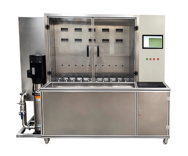
Performance and Durability Test Bench for Water Pumps And Valves
Water pumps and valves are used in many places that people depend on every day, from household water supply systems and commercial buildings to industrial production lines and water treatment facilities. Although these products may look simple from the outside, their performance depends on several factors working together. A pump needs to deliver the required flow and pressure, while a valve must control the flow and provide the required sealing performance. If either product fails to meet its specifications, the result may be water leakage, unstable operation, increased energy consumption, or unexpected maintenance costs.
At Guangzhou Chuangge Automation Equipment Co., Ltd., we specialize in customized testing equipment. We understand that manufacturers need more than a machine that simply turns on a product and checks whether it runs. They need a practical way to measure performance, repeat test conditions, record results, and identify problems before products are delivered to customers.
Our Performance/Durability Test Bench for Water Pumps and Valves is a customized equipment solution planned around the product type, test procedure, and operating requirements. Depending on the approved project scope, the system may be designed to evaluate pump flow rate, pressure, head, power consumption, valve pressure resistance, leakage, operating cycles, and other specified performance indicators. The available functions depend on the selected configuration rather than a fixed standard package.
We work with customers to clarify what needs to be tested, how the result will be judged, and what information must be saved. This helps us design a Water Pump Performance Test bench, valve durability test bench, or combined pump and valve testing system that fits the customer's production or laboratory workflow.
1. Understanding the Performance and Durability Test Bench for Water Pumps and Valves
Why do manufacturers need a dedicated test bench?
A product can pass a quick visual inspection and still have problems that only appear during operation. A pump may run but fail to deliver its required flow. Its pressure may change when the operating point changes, or its power consumption may be higher than expected. A valve may open and close normally but still leak when exposed to a specified pressure. Repeated operation may also reveal wear or changes in sealing performance.
A dedicated performance and durability test bench gives manufacturers a controlled way to check these characteristics. Instead of relying only on appearance or a short manual check, operators can run a defined test procedure and compare the measured results with agreed requirements.
For water pumps, performance testing commonly focuses on the relationship between flow rate, pressure head, rotational speed, and input power. These values help engineers understand how the pump behaves under different operating conditions. The exact measurements depend on the pump type and the test specification.
For valves, the focus may be different. A pressure test can examine whether the valve body and pressure-containing parts withstand the specified conditions. A closure test can help determine whether the valve meets the required leakage limit when closed. A durability test may involve repeated opening and closing, followed by checks to see whether the valve continues to operate as required.
These tests are related, but they are not interchangeable. A valve that passes a pressure test has not automatically demonstrated long-term cycling durability. Likewise, a pump that operates for a long time has not necessarily met its required hydraulic performance values. We therefore recommend defining each test objective separately when preparing the equipment plan.
What can a customized test bench include?
The equipment configuration depends on the product range and test method. A pump testing system may include a water circulation loop, sample mounting fixtures, pressure sensors, flow measurement instruments, temperature sensors, an electrical power meter, a control cabinet, and data-recording software. Where required, the system may also include speed measurement or other project-specific monitoring functions.
A valve testing system may require a pressure source, water or another specified test medium, pressure gauges or sensors, sealing fixtures, clamping mechanisms, controlled valves, and a means of checking leakage. If the project includes automatic endurance testing, an actuator and cycle counter may also be required.
For a combined pump and valve test bench, we review whether the two product groups can share parts of the system or require separate circuits and fixtures. Sharing a water supply or data system may be practical in some projects, but it should not compromise the required test conditions, measurement quality, or safety. A combined system is useful only when its layout supports the actual test procedures.
During technical discussions, we focus on the following questions:
Which pump or valve models will be tested?
What are the product dimensions, connection sizes, rated pressure, and electrical requirements?
Which performance indicators need to be measured?
Does the test require static pressure, flowing water, repeated operation, or a combination of procedures?
How many samples must be tested at the same time?
Which standards or customer procedures define the test conditions?
What measurement accuracy, alarm functions, and report fields are required?
What installation space, utilities, and operator access are available?
These details help us select an appropriate design. We do not assume that every pump or valve can use the same pressure source, flow meter, fixture, or control sequence. The final solution should reflect the product's intended use and the test requirements agreed with the customer.
2. Working Principle: From Sample Installation to Test Report
The basic principle of a performance and durability test bench is to apply defined conditions to a product, measure its response, and compare the results with specified limits. The individual steps depend on whether the equipment is designed for pump performance, valve pressure testing, valve endurance, or an integrated testing application.
Step 1: Confirm the test procedure
Before testing starts, the operator or engineer confirms the sample model, test objective, required conditions, and acceptance criteria. For a water pump, the procedure may specify several flow points, corresponding pressure head measurements, input power, and the operating duration at each point. For a valve, the procedure may define the test pressure, holding time, valve position, test medium, leakage observation method, and any required cycling sequence.
These values should come from the relevant product standard, approved technical specification, or customer test procedure. There is no single pressure or duration suitable for every pump and valve. Using a generic value without checking the product requirements can lead to misleading results or unsafe testing.
Step 2: Install and connect the sample
The sample is mounted in the designated fixture and connected to the test circuit. For a pump, this may involve connecting the inlet and outlet pipes, checking the direction of flow, securing the unit, and arranging the required electrical supply. For a valve, the operator must ensure that the correct connections, seals, clamping arrangement, and flow direction are used where applicable.
Good fixture design matters. A connection that is poorly aligned can create unwanted stress, while a loose joint may cause leakage that is unrelated to the sample itself. The test bench should provide enough access for sample loading, inspection, and removal without making the operator's job unnecessarily difficult.
Step 3: Check the system before applying the test condition
Before the main test begins, the operator checks the connections, instruments, guards, and safety arrangements. A water-based circuit may need to be filled and purged of trapped air when required by the procedure. The operator should also verify that the selected sensors, pressure range, flow range, and power supply are suitable for the test.
For pressure testing, the system must be designed for the maximum approved test conditions. Pressure-containing components, fixtures, connections, and protective measures should be selected according to the engineering design and applicable safety requirements. The test should never exceed the approved operating limits of the equipment or sample.
Step 4: Run the performance test
During a pump performance test, the system operates the sample under defined conditions and collects the required measurements. A typical hydraulic test may measure flow rate and pressure head at several operating points. Electrical input power may also be measured when the project requires an assessment of energy use or overall operating performance.
The test bench can be configured to display the measured values in real time. Depending on the project, it may also calculate derived values, plot performance curves, compare results with configured limits, or save records for later review. These functions must be defined during the design stage because not every system automatically includes every calculation or reporting feature.
For a valve pressure test, the system applies the specified pressure and holds it for the required period. The operator or configured measurement method then checks the relevant pressure behavior and leakage criteria. The test sequence depends on whether the objective is to assess the pressure boundary, valve closure, or another defined characteristic.
Step 5: Carry out the durability test
A durability test looks at how the product behaves over repeated operation or a defined period of use. For valves, this may involve repeated opening and closing cycles. The equipment may use an actuator to move the valve between specified positions and a counter to record the number of completed cycles. Other functions may monitor actuation time, operating force, leakage, or changes in performance where required.
For pumps, durability testing can involve extended operation under selected working conditions. The test plan may include monitoring temperature, pressure, flow, power consumption, vibration, or other indicators relevant to the product. The purpose is to identify changes during operation and determine whether the pump continues to meet the agreed criteria.
Durability testing does not automatically predict the exact service life of a product. A test performed for a defined period or number of cycles provides evidence about performance under those particular conditions. Any claim about expected lifetime needs an appropriate test method and a sound basis for interpretation.
Step 6: Evaluate results and save records
After the test, the recorded measurements are compared with the approved acceptance criteria. The result may be judged against a maximum or minimum value, an allowable range, a leakage limit, a specified number of cycles, or a combination of requirements.
A useful test report identifies the sample, model, test date, test conditions, measurement results, alarms or interruptions, and final evaluation. If the system is used for batch quality control, sample identification and record consistency become particularly important. They help engineers trace an abnormal result back to the product and the test conditions.
We can discuss the required data fields and report format during customization. Where customers need automatic pass/fail evaluation, the decision rules should be documented and verified. Some tests may still require manual inspection or engineering review, so the system should not be presented as an automatic substitute for every compliance decision.
3. Main Test Functions and Technical Advantages
Water pump flow and pressure head measurement
Flow rate describes how much liquid passes through a system in a given period. Pressure head describes the energy the pump adds to the liquid, expressed as the height of a liquid column. These values are closely related to a pump's operating point and are important when checking whether the pump can meet the required duty.
A customized Water Pump Performance Test Bench can be designed to measure these values at specified operating points. By recording several points, engineers can develop a performance curve showing how the pump behaves as the flow changes. This information is useful for production inspection, product development, and comparison with the manufacturer's declared performance.
Measurement quality depends on more than the sensor alone. The piping arrangement, installation position, flow stability, pressure measurement points, instrument range, and test procedure can all affect the result. We review these factors when planning the test system and selecting the measurement equipment.
Electrical input power and operating monitoring
For electrically driven pumps, the test may include input voltage, current, electrical power, or other electrical parameters. These values can help engineers understand the operating condition and compare samples tested under the same conditions.
The electrical measurement configuration depends on the motor and drive system. Single-phase and three-phase products may require different measurement arrangements. If the pump uses a variable-speed drive or electronic controller, the test procedure should also define the relevant speed and operating settings.
Where the customer needs extended operation, temperature monitoring or other condition monitoring may be included. The selected sensors and alarm limits should reflect the product design and test objective rather than generic assumptions.
Valve pressure resistance and sealing checks
Valve pressure testing generally addresses specific questions about the product's pressure boundary and closure performance. A shell or pressure-boundary test checks the relevant parts under the defined test condition. A closure test focuses on leakage through the closed valve under the specified procedure.
Depending on the valve design and applicable standard, the system may use water or another approved test medium. It may also need different fixtures for different connection types or sizes. The equipment should provide a controlled way to apply and monitor pressure while allowing the required leakage observation or measurement.
We recommend keeping the pressure source, fixture, pipework, seals, sensors, and protective arrangements within a clearly defined engineering scope. The test bench should be selected for the required test range and the relevant safety considerations, not simply for the highest pressure that appears in a product catalogue.
Valve opening and closing durability
Some valves are expected to operate repeatedly during their service life. A valve durability test bench can be designed to perform a defined number of operating cycles and record whether the valve continues to function as required. Depending on the project, the system may use pneumatic, electric, or another suitable actuation method.
The appropriate actuator depends on the valve type, operating torque or force, travel, speed, and required control sequence. The test fixture must also hold the sample securely without interfering with its normal operation. If leakage or functional performance must be checked after cycling, those checks should be included in the agreed test plan.
Automation and multi-sample testing
For production applications, automated sequences can reduce repetitive manual work and make the test process easier to standardize. Depending on the design, the operator may select a test program, load the sample, start the procedure, and monitor progress from a control interface.
Multiple test stations may be useful when a manufacturer needs to test several samples in parallel. However, the number of stations should be chosen according to the required test capacity, available utilities, physical space, instrument arrangement, and safety requirements. More channels are not always more efficient if they make sample handling or troubleshooting difficult.
Data logging and fault identification
Data logging helps operators see what happened during the test rather than relying only on a final reading. A record may contain pressure and flow measurements, cycle count, operating time, electrical parameters, alarms, and test status, depending on the system configuration.
When an abnormal result appears, a clear record can help engineers determine whether the issue is related to the sample, the test condition, a connection, or an instrument. This does not eliminate the need for technical investigation, but it provides a more useful starting point than a simple pass/fail label.
Comparison table: pump and valve testing requirements
| Test objective | Typical measured or observed items | Possible equipment functions |
|---|
| Pump hydraulic performance | Flow rate, pressure head, operating point | Water circuit, flow measurement, pressure sensors, data recording |
| Pump electrical performance | Voltage, current, input power, selected operating status | Electrical supply, power measurement, monitoring interface |
| Pump endurance | Operating time, selected performance changes, temperature where required | Continuous operation control, sensors, alarms, event logging |
| Valve pressure boundary | Pressure behavior and visible evidence of leakage, as applicable | Pressure source, pressure measurement, suitable fixtures and protection |
| Valve closure tightness | Leakage under the specified closed-valve test conditions | Pressure control, sealing fixture, leakage observation or measurement |
| Valve operating durability | Cycle count, operation status, post-cycle condition | Actuator, sequence control, cycle counter, optional monitoring |
Source: Engineering overview prepared for product planning based on common pump and valve test objectives. The listed functions are examples, not a claim that every configuration includes all items. Refer to the applicable product standard and approved technical specification for required test methods and acceptance limits.
4. Standards and How We Plan a Suitable Test Solution
When a customer asks for a performance or durability test bench, one of our first questions is which standard or test procedure the product must follow. Standards help define how a test is performed, which measurements are required, and how the results should be evaluated. However, the correct reference depends on the product category and the intended test.
We encourage customers to provide the exact standard number, edition, relevant clauses, and any internal acceptance procedure. If the customer is preparing products for a particular market or certification process, that information should be considered during the initial technical review.
ISO 9906 for rotodynamic pump performance testing
ISO 9906:2012, titled Rotodynamic Pumps — Hydraulic Performance Acceptance Tests — Grades 1, 2 and 3, specifies hydraulic performance acceptance tests for rotodynamic pumps, including centrifugal, mixed-flow, and axial-flow pumps. The International Organization for Standardization describes its use for customer acceptance testing at pump test facilities, including manufacturer facilities and laboratories.
The standard includes different acceptance grades with different tolerance requirements. This matters because the required measurement quality and acceptance criteria should be agreed according to the intended application. A pump test bench must be configured to support the relevant test points and measurements required by the selected procedure.
For a project based on ISO 9906, we would clarify the pump type, rated operating conditions, required flow and head measurements, input power requirements if applicable, and the agreed acceptance grade. Additional measurements, such as net positive suction head, should be included only when required by the project scope and supported by the proposed equipment.
ISO 5208 for industrial metallic valve pressure testing
ISO 5208:2015, Industrial Valves — Pressure Testing of Metallic Valves, specifies examinations and tests intended to establish the integrity of a valve's pressure boundary and verify closure tightness and the structural adequacy of its closure mechanism. ISO notes that this standard is intended to be used alongside the applicable valve product standard where referenced.
This distinction is important. ISO 5208 is not a universal specification for every valve and every test requirement. The relevant product standard may set additional or different requirements. The standard also states that it does not cover the safety aspects of pressure testing, so the test equipment still needs a separate and appropriate safety design.
For a valve pressure test bench, we therefore need to know the valve material, type, size, connection arrangement, specified test medium, test pressure, holding time, leakage criteria, and applicable product requirements. These details influence the pressure source, fixture, control system, instrumentation, and protective arrangements.
API Standard 598 for valve inspection and testing
API Standard 598, Valve Inspection and Testing, is another reference that may be relevant to certain industrial valves. The American Petroleum Institute's standard covers inspection, examination, supplementary examinations, and pressure-test requirements for specified valve types, including gate, globe, plug, ball, check, and butterfly valves.
Whether API 598 applies depends on the valve, the governing product standard, the purchaser's requirements, and the project agreement. It should not be assumed that all valves need the same sequence or acceptance criteria. The correct edition and any referenced requirements should be confirmed before the test bench is designed.
Reference table: selecting standards for test planning
| Reference | Main subject | How it may inform equipment design |
|---|
| ISO 9906:2012 | Hydraulic performance acceptance testing of rotodynamic pumps | Helps define pump performance measurements and acceptance requirements |
| ISO 5208:2015 | Pressure testing of industrial metallic valves | Helps define relevant pressure-boundary and closure-tightness test requirements |
| API Standard 598, 11th Edition, 2023 | Inspection and testing of specified industrial valve types | May inform valve inspection and pressure-test sequences when applicable |
Sources: Official ISO pages for ISO 9906:2012 and ISO 5208:2015; API Standard 598 edition information from Accuris standards catalogue. Standards and editions must be checked against the project requirements before use. Listing a reference here does not mean that every customized system automatically complies with it.
For us, the practical lesson is simple: the test bench should follow the required procedure, not the other way around. Once the applicable requirements are clear, we can discuss the sensors, pressure capacity, flow range, fixtures, control logic, safety functions, and reporting features needed for the application.
5. Applications in Pump Manufacturing, Valve Production, and Related Industries
Water pump manufacturing
Pump manufacturers may use a performance test bench to check finished products before shipment, compare production batches, or verify changes to a pump design. A defined test process helps the manufacturer understand whether the pump meets the required flow and pressure conditions.
For production inspection, the test sequence should be practical and repeatable. Operators need to connect the sample, run the required points, review the result, and remove the pump without unnecessary handling. Where a range of pump models shares the same test station, interchangeable fixtures and clear model selection may help make changeovers easier.
Industrial and commercial pump systems
Pumps used in commercial buildings, industrial facilities, and water treatment applications can have different capacities and operating requirements. A laboratory test bench may be designed to handle selected product families, with the hydraulic circuit and instruments matched to their specified operating range.
If the manufacturer needs to test a wide range of models, it is important to identify the smallest and largest products, the expected flow and pressure ranges, the drive arrangements, and the required test points. A system designed around only one model may not be suitable for a much larger or higher-capacity pump without modification.
Valve manufacturing and quality inspection
Valve manufacturers may need to check pressure integrity, closure tightness, operating function, and durability according to the applicable product requirements. A customized valve test bench can help standardize fixture installation and test execution across a defined product family.
Valve design affects the equipment requirements. Ball valves, gate valves, butterfly valves, and check valves do not all operate in the same way. Their connection geometry, operating mechanism, pressure requirements, and leakage evaluation methods may differ. We therefore recommend grouping products by their actual testing needs before deciding on a shared fixture or common test station.
Water treatment and fluid-control equipment
Water treatment systems use pumps and valves to move and control liquids through different process stages. Manufacturers of related equipment may need to verify individual components or evaluate an assembled unit under defined conditions.
The testing setup depends on whether the project concerns a standalone pump, a valve, or a larger assembly. If several components are tested together, the test plan should identify which measurements belong to each component and which results describe the overall system. This helps avoid drawing conclusions from data that does not directly represent the product being evaluated.
Research and development laboratories
During product development, engineers often compare different designs, materials, impeller configurations, seals, or control settings. A test bench with suitable measurement and data-recording functions can help them observe how changes affect performance under the same test conditions.
For research applications, flexibility may be more important than maximum production throughput. Engineers may need to change the operating point, add a measurement channel, or export detailed records. These requirements should be discussed before the equipment design is finalized so that the system is neither too limited nor unnecessarily complicated.
Incoming inspection and supplier quality control
Companies that purchase pumps or valves from different suppliers may use a defined test procedure to verify selected characteristics. The acceptance criteria should be consistent with the purchase specification, applicable standards, and intended use.
A well-planned test record can help a quality team compare samples from different batches and follow up on recurring issues. The equipment should support the required test method, but the final inspection decision remains tied to the agreed criteria and the customer's quality process.
6. Custom Design, Manufacturing, Inspection, and Delivery
At Guangzhou Chuangge Automation Equipment Co., Ltd., we focus on customized testing equipment for industrial applications. Our work starts with understanding the customer's requirements and developing a solution around them. For a pump and valve test bench, the design must account for both the product's physical characteristics and the measurements needed to evaluate it.
Requirement review
We begin by collecting product drawings, technical specifications, sample photographs, operating instructions, and any available test procedures. We also ask about the target product range, expected test capacity, applicable standards, required measurements, and acceptance criteria.
At this stage, we discuss the available factory utilities, including electrical power, water supply, drainage, ventilation, and installation space where relevant. These details can affect the test circuit, equipment layout, control cabinet, and maintenance access. If a project requires a closed water circulation system or a special test medium, that requirement should be identified early.
Technical proposal and configuration
After reviewing the requirements, we prepare a proposed configuration for customer confirmation. The technical scope may include the mechanical frame, sample fixtures, pressure or flow measurement, electrical control, automation, safety measures, software functions, and documentation.
We recommend documenting important parameters in a technical agreement. These may include the product models covered, rated operating range, required test points, instrument specifications, channel count, cycle requirements, alarm logic, data fields, acceptance method, and accessories. Clear documentation helps both sides understand what the system is expected to do.
Mechanical fabrication and component assembly
Once the configuration is approved, manufacturing and assembly follow the project design. Depending on the system, this may involve fabrication of the frame, installation of piping and fixtures, mounting of sensors, assembly of electrical components, control cabinet wiring, and integration of the software.
We pay attention to the accessibility of connections and routine service points. For a pump test bench, piping layout and instrument positions can influence the ease of operation and the quality of measurement. For a valve test bench, the fixture should support secure sample installation and allow the required pressure test to be carried out under the approved safety arrangements.
Control integration and function checks
The control system is configured according to the agreed test sequence. Depending on the application, it may manage pump operation, pressure settings, valve actuation, test timing, measurement display, alarms, and data recording. Any automatic pass/fail function must use the criteria confirmed by the customer.
During functional inspection, the system is checked according to the agreed scope. The specific checks depend on the equipment configuration and may cover control response, measurement display, channel operation, sequence execution, alarm behavior, data recording, and other defined functions.
Performance verification before delivery
Before delivery, each unit undergoes functional inspection and performance verification according to the agreed project requirements. Where measurement performance is important, the verification method and acceptance limits should be defined in advance. Calibration requirements for pressure sensors, flow meters, power meters, and other instruments should also be clarified as part of the project scope.
We avoid treating a general power-on check as proof of every technical capability. A meaningful acceptance procedure should identify what is checked, how it is checked, what results are expected, and which records will be supplied. This gives the customer a clear basis for reviewing the equipment before shipment or during commissioning.
Documentation and operator handover
Operating instructions and technical documentation are provided as agreed. Depending on the project, the document package may include equipment specifications, operating procedures, wiring information, maintenance guidance, and inspection records. If the customer requires a particular document language or format, it should be confirmed during the technical review.
We also recommend preparing an operating procedure for the customer's team. It should cover sample installation, pre-test checks, normal operation, response to alarms, safe depressurization where relevant, and routine maintenance. Clear operating rules help reduce avoidable mistakes and support consistent test results.
Production lead time, packaging, and transportation
Our typical production cycle for customized testing equipment is approximately 30 to 60 days, depending on the equipment specifications and customization requirements. The actual schedule may be affected by design complexity, special fixtures, component availability, software functions, and the time needed for technical confirmation and inspection.
Before shipment, we use protective materials and sturdy wooden cases where appropriate to help protect the equipment during transport. The packaging method depends on the equipment dimensions, weight, fragile components, and shipping route. Products can be shipped by sea, air, or land according to the customer's destination and schedule.
Payment terms are negotiable and should be confirmed in the commercial agreement. We recommend confirming the technical scope, delivery location, transportation method, inspection requirements, documentation, and payment milestones before the order is finalized.
Company background and quality management
Guangzhou Chuangge Automation Equipment Co., Ltd. specializes in customized testing equipment used across sectors such as construction materials and components, wires and cables, plastics and textiles, electrical plugs, sockets and switches, electronic products, and home appliances. Our approach is to review the requirements of each application and develop equipment around the defined test procedure.
According to our company information, we have obtained ISO 9001 quality management, ISO 14001 environmental management, and ISO 45001 occupational health and safety management system certifications. Our intellectual property portfolio includes more than 20 patents, covering invention patents, utility model patents, and software-related patents.
These credentials form part of our company background. For a specific pump and valve test bench, we still recommend reviewing the technical proposal, the agreed inspection procedure, and the documented performance requirements. This is the most practical way to confirm whether the proposed solution meets the customer's needs.
7. How to Choose the Right Pump and Valve Test Bench
When comparing testing equipment suppliers, it is tempting to focus on the quoted price or the number of functions listed in a brochure. In practice, the most useful system is the one that can perform the required tests consistently, fit the available space, and be operated safely by the intended users.
Start with the product range
List the pump or valve models that the equipment must handle. Include their dimensions, connection types, rated pressure, flow range where applicable, electrical requirements, and expected operating conditions. If several models need to share the same test bench, identify which fixtures can be common and which need to be changed.
Define measurements before choosing instruments
Decide which values must be measured and what level of measurement performance is required. A pump performance test may need flow, pressure head, and input power. A valve pressure test may require controlled pressure and a defined method for evaluating leakage. Instrument selection should follow these needs.
It is also worth asking how the instruments will be installed, checked, and maintained. A high-specification sensor cannot compensate for a poorly arranged test circuit or an unclear procedure. The whole measurement chain needs to be considered.
Consider daily operation
Think about who will use the equipment and how often samples will be changed. A production line may need quick loading and a straightforward interface. A research laboratory may need more flexible settings and detailed records. A system used for both purposes may require a different balance of functions.
Check safety and maintenance needs
For pressure testing, confirm the rated capacity of pressure-containing components and fixtures, the protective measures, and the safe procedure for releasing pressure. For electrically driven pumps, consider electrical protection, grounding, moving parts, and access during operation. Maintenance requirements should be understood before the system is installed.
Agree on acceptance criteria and documentation
Before ordering, confirm how the equipment will be inspected and accepted. The agreement should state the required functions, test conditions, measurement requirements, and documents. If the system must communicate with existing factory software or export data in a particular format, those details should also be included.
Taking time to clarify these points at the start helps avoid expensive changes later. It also gives the supplier a clearer basis for preparing a practical proposal.
8. Frequently Asked Questions
Q1: What is a Performance/Durability Test Bench for Water Pumps and Valves?
It is a testing system designed to evaluate selected performance and durability characteristics of water pumps, valves, or both. Depending on the configuration, it may measure pump flow and pressure, monitor electrical input, perform valve pressure or leakage tests, or automate repeated valve operation. The final functions depend on the product and test requirements.
Q2: Can one test bench test both water pumps and valves?
Yes, a combined solution may be possible when the product range and test procedures are suitable. However, pump hydraulic testing and valve pressure testing have different requirements. The system may need separate circuits, fixtures, or operating modes. We review the required products and tests before confirming whether an integrated design is practical.
Q3: Which pump parameters can the equipment measure?
Depending on the project, the system may measure flow rate, pressure head, electrical input power, voltage, current, rotational speed, temperature, or other specified values. Not every configuration includes all measurements. The required parameters and measurement performance should be agreed before the instruments are selected.
Q4: Can the test bench check valve leakage?
A valve test bench can be designed for leakage evaluation when the required test method, pressure conditions, valve position, test medium, and acceptance criteria are defined. The method may differ according to valve type and the applicable standard. The final configuration should clearly specify how leakage is observed or measured.
Q5: Can the system perform automatic valve cycling?
Automatic cycling can be included when required by the project. The system may use an actuator, cycle counter, sequence control, and selected monitoring functions. The actuator type and operating sequence depend on the valve's mechanism, operating force or torque, travel, and required test conditions.
Q6: Which standards can the equipment support?
Relevant references may include ISO 9906 for hydraulic performance acceptance testing of rotodynamic pumps, ISO 5208 for pressure testing of industrial metallic valves, or API Standard 598 for inspection and testing of specified industrial valve types. The applicable standard and edition must be confirmed for the product and target market. The equipment scope should be mapped to the relevant test clauses rather than assuming that all standards apply to every product.
Q7: Can test results be stored and exported?
Data recording and export can be discussed during customization. Depending on the project, records may include sample identification, measured values, test conditions, test duration, cycle count, alarms, and final status. The report format and storage requirements should be confirmed before production so the system can support the customer's quality workflow.
Q8: How many samples can be tested at one time?
The number of samples depends on the product dimensions, required test conditions, power and water capacity, fixture design, measurement arrangement, and available space. We recommend confirming the target throughput and the full product range before deciding on the number of stations.
Q9: How long does manufacturing take?
The typical production cycle is around 30 to 60 days, depending on the specifications and customization requirements. The confirmed lead time may vary with design complexity, component availability, special fixtures, and software functions. We provide the expected schedule during technical and commercial discussions.
Q10: What inspection is carried out before delivery?
Each unit undergoes functional inspection and performance verification according to the agreed project scope. The checks may cover control functions, instrument display, test sequences, alarms, data recording, and other specified items. Any special acceptance test or required inspection record should be agreed before manufacturing is completed.
Q11: What information is needed for a quotation?
Please provide the product name and model, drawings or photographs, dimensions, connection type, rated pressure, flow range for pumps, electrical requirements, test objective, applicable standards, required measurements, target sample quantity, and expected test procedure. If you need data export, automatic evaluation, or special fixtures, include those requirements as well. We can then review the information and clarify any open points.
Q12: What are the payment and shipping arrangements?
Payment terms are negotiable and should be confirmed in the commercial agreement. Transportation can be arranged by sea, air, or land according to the destination and delivery schedule. Protective materials and sturdy wooden cases are used as appropriate to protect the equipment. Shipping terms, insurance, customs requirements, and delivery arrangements should be confirmed for each order.
Request a Customized Performance and Durability Test Bench
Choosing a suitable test bench begins with a clear understanding of the product and the test objective. Whether you manufacture water pumps, industrial valves, or related fluid-control equipment, the test system should be designed around the measurements, operating conditions, and acceptance criteria that matter to your business.
At Guangzhou Chuangge Automation Equipment Co., Ltd., we provide customized testing equipment based on confirmed project requirements. We can discuss the equipment structure, measurement functions, fixtures, control logic, safety arrangements, data recording, and inspection scope with your team. Our aim is to develop a practical solution that supports consistent testing and helps your engineers make informed quality decisions.
To start a project discussion, share your product specifications, test procedure, applicable standards, required test capacity, and preferred reporting format. Drawings, photographs, and sample information are useful when available. We can review the requirements and clarify the technical scope before preparing the final proposal.
Our typical manufacturing lead time is 30–60 days, depending on the level of customization. Before delivery, each unit undergoes functional inspection and performance verification according to the agreed requirements. Operating instructions and technical documentation are supplied as agreed, while payment and shipping arrangements can be discussed for your project.
Contact Guangzhou Chuangge Automation Equipment Co., Ltd. to discuss a customized Performance/Durability Test Bench for Water Pumps and Valves that matches your product specifications and testing workflow.
Technical References
Technical note: The references above are provided to help readers identify potentially relevant test standards. Their applicability depends on the product, destination market, governing product standard, and agreed test procedure. Test pressure, flow range, measurement accuracy, cycle count, leakage limit, and acceptance criteria are not universal values; they must be specified and confirmed for each project.


