Fire Resistance Testing Machine for Electric Wires And Cables: Working Principles, Applications, and Customized Testing Solutions
When an electrical cable is exposed to fire, the most important question is not simply whether its outer jacket burns. In many applications, the cable must continue carrying electrical signals or power for a specified period, even while exposed to high temperatures and other test conditions. Emergency lighting, fire alarm systems, communication networks, and other safety-related installations may depend on this ability.
This is why a Fire Resistance Testing Machine for Electric Wires and Cables is an important piece of equipment for cable manufacturers, quality control departments, research laboratories, and third-party testing organizations.
At Guangzhou Chuangge Automation Equipment Co., Ltd., we specialize in customized testing equipment. We understand that different cable products, test methods, and laboratory requirements call for different equipment configurations. Our approach is to begin with the actual testing objective, clarify the applicable standard, and then develop a suitable technical solution rather than assume that one machine can meet every requirement.
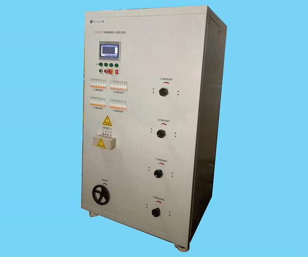
A cable fire resistance tester is designed to expose a prepared cable specimen to specified fire conditions and help determine whether it maintains the required electrical circuit integrity during the test. Depending on the selected method, the equipment may include a heating or burner system, a specimen support frame, a temperature monitoring arrangement, an electrical continuity monitoring system, a control unit, and protective components.
The exact configuration depends on the intended test method. Some methods require mechanical shock during fire exposure, while others use different arrangements or additional conditions. We therefore recommend confirming the standard and its applicable edition before finalizing a machine design.
What does cable fire resistance testing actually measure?
In practical terms, the test examines how a cable behaves under defined fire exposure. For a circuit integrity test, the central concern is whether the required electrical circuit remains functional throughout the specified test period. The result is not determined by appearance alone. A cable may retain part of its external shape while its internal conductors or insulation fail to maintain electrical continuity.
A Fire Resistance Testing Machine for Electric Wires and Cables can support several stages of product development and quality management:
Evaluating the performance of fire-resistant cable designs under specified conditions.
Comparing cable samples made with different insulation, sheath, or protective constructions.
Investigating failures that occur during fire exposure.
Supporting routine quality control and product development activities.
Generating test records for internal evaluation or for submission to an appropriate testing organization, where required.
It is important to distinguish fire resistance from flame retardancy. Flame retardancy generally concerns how readily a material or product ignites and how burning develops under a specified method. Fire resistance testing for cables may instead focus on maintaining circuit integrity during exposure to fire. Smoke density, heat release, and flame spread are also separate properties with their own test methods.
A single test result cannot automatically represent every aspect of cable fire performance.
Who needs this testing equipment?
Cable manufacturers may use a fire resistance testing machine during product development, manufacturing quality checks, and technical investigations. Electrical engineering companies and cable system suppliers may need access to relevant test data when selecting products for projects. Research institutions can use the equipment to investigate the behavior of cable constructions under controlled conditions.
Testing laboratories have another requirement: repeatability. They need a setup that can be configured according to the selected method, operated consistently, and supported by suitable records. A well-planned machine should make it easier to control test conditions, monitor the specimen, and document the result.
For us, the first step in a project is always to understand which of these tasks the customer needs to perform.
2. Working Principle: How a Cable Fire Resistance Test Is Conducted
The working principle of a Fire Resistance Testing Machine for Electric Wires and Cables is straightforward at a basic level: a prepared cable specimen is installed in a defined test arrangement, exposed to the required fire conditions, and monitored for the performance specified by the applicable method.
However, reliable testing involves more than placing a cable near a flame. Specimen preparation, mounting, temperature control, electrical monitoring, and the timing of the test all affect the quality and meaning of the result.
Step 1: Prepare and identify the cable specimen
Before a test begins, the operator needs to identify the cable type and prepare the specimen according to the selected standard. Relevant details may include conductor construction, rated voltage, overall diameter, insulation material, protective layers, and specimen length.
These details matter because cables that look similar from the outside may have very different internal constructions. A single-core cable, a multicore cable, an armoured cable, and a cable with a large overall diameter may require different mounting arrangements or test procedures.
The specimen must also be installed according to the required bending radius, support spacing, and other applicable conditions. Incorrect mounting can affect the way heat reaches the cable or the way mechanical forces are transferred to it.
We recommend confirming the specimen dimensions and mounting requirements before manufacturing the machine. This helps avoid a situation in which a customer receives equipment that cannot accommodate the intended cable samples.
Step 2: Install the specimen and configure the test system
The prepared cable is fixed to the designated support structure. Depending on the test method, the system may also require electrical connections, a circuit monitoring arrangement, a burner assembly, and temperature measurement components.
The electrical monitoring arrangement is especially important when the test concerns circuit integrity. The purpose is to detect whether the cable continues to satisfy the specified electrical continuity or circuit performance requirement during the exposure period.
The test circuit must be configured according to the applicable method. Voltage, current, fuse selection, monitoring points, and failure criteria should not be chosen simply because they worked for another cable test. The standard and the specific cable application determine what is appropriate.
Step 3: Apply the specified fire conditions
The machine applies the prescribed fire exposure using the heating arrangement defined by the test method. In a burner-based system, the burner, fuel supply, air supply, and control components work together to establish the required conditions.
For example, IEC 60331-1:2018 describes a fire-with-shock test method at a temperature of at least 830°C for applicable cables with an overall diameter greater than 20 mm. IEC 60331-2:2018 addresses the corresponding method for applicable cables with an overall diameter not exceeding 20 mm. Both documents focus on circuit integrity under specified fire and mechanical shock conditions.
These examples are useful when discussing the design of a cable fire resistance testing machine, but they should not be treated as universal settings for every cable test. Other methods may have different temperature profiles, mounting arrangements, exposure periods, and acceptance criteria.
During operation, the machine should allow the operator to follow the required test sequence and monitor relevant parameters. If the selected method includes mechanical shock, the equipment must also provide the appropriate shock arrangement and timing.
Step 4: Monitor circuit integrity and record the result
While the specimen is exposed to the test conditions, the monitoring system checks the electrical response required by the selected method. If the cable fails to maintain the specified circuit function, the operator records the event according to the applicable procedure.
The observation may include the time at which failure occurs, the relevant electrical response, the test conditions, and any other information required for the test report.
A useful test record should identify the specimen and the method used. It should also distinguish actual observations from conclusions drawn from those observations. For example, a cable that maintains circuit integrity for a specified period under a particular test method has demonstrated performance under those conditions. This does not automatically establish performance under every fire scenario or every installation condition.
Typical testing workflow
| Stage | Main activity | Information to control or record |
|---|
| 1. Specimen preparation | Prepare and identify the cable sample | Cable type, construction, dimensions, sample identification |
| 2. Installation | Mount the specimen and connect the required circuits | Mounting arrangement, electrical connections, support position |
| 3. System verification | Check the burner, monitoring system, and relevant controls | Applicable setup checks and operating conditions |
| 4. Fire exposure | Apply the test conditions specified by the selected method | Temperature, exposure sequence, duration, and other required parameters |
| 5. Monitoring | Observe the electrical response and specimen behavior | Continuity status, failure events, and relevant observations |
| 6. Reporting | Review and document the test outcome | Test method, specimen details, recorded data, and conclusion |
Source: Workflow summary based on the test objectives and scope described in IEC 60331-1:2018 and IEC 60331-2:2018. The table is an explanatory overview, not a substitute for the complete procedures in the standards.
Why temperature control and monitoring matter
A fire resistance test is meaningful only when the exposure conditions are sufficiently controlled for the intended method. If the heating conditions vary significantly, the comparison between two cable samples may become unreliable.
Temperature measurement, burner control, electrical monitoring, and consistent specimen installation therefore deserve attention during equipment selection. The importance of each component depends on the standard, the cable design, and the intended use of the results.
For a customized system, we discuss these requirements with the customer before confirming the final configuration.
3. Main Features and Technical Considerations When Selecting Equipment
A suitable Fire Resistance Testing Machine for Electric Wires and Cables should be designed around the test method, not simply around a general product description. Customers sometimes begin their search by comparing machine dimensions or prices. Those details matter, but they do not answer the most important question: can the equipment perform the test that the laboratory actually needs?
At Guangzhou Chuangge Automation Equipment Co., Ltd., we focus on matching the equipment configuration to the customer's test requirements.
Heating and burner system
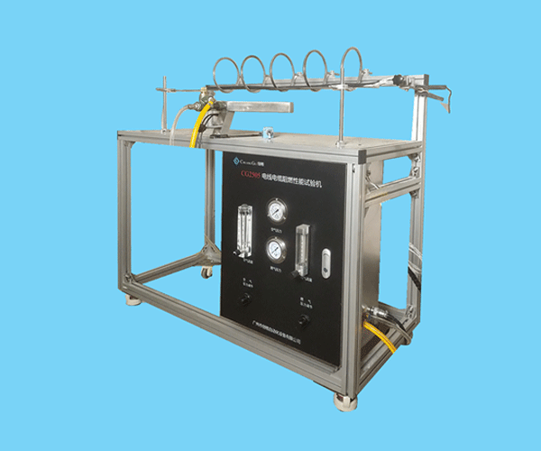
The heating arrangement creates the fire exposure required by the applicable method. Depending on the design, the system may include a burner, fuel and air supply components, flow control devices, ignition components, temperature sensors, and a protective enclosure.
The burner and control arrangement must be appropriate for the intended standard. Where the method specifies particular fuel and air control requirements, those requirements need to be reflected in the design and verification plan.
For example, IEC 60331-1:2018 includes requirements relating to verification of the burner and control system, and describes the use of mass flow meters or controllers to control fuel and air input accurately. This is one reason we do not treat burner selection as a generic decision independent of the chosen test method.
Specimen support and mounting structure
The support frame holds the cable in the required position during testing. It should provide suitable access for specimen installation, electrical connections, temperature measurement, and any additional components required by the selected procedure.
Cable diameter and construction can affect the mounting arrangement. A large cable may need different support spacing or bending provisions from a small cable. The equipment design should therefore be checked against the actual specimen dimensions and the standard's requirements.
A well-planned mounting system also makes routine operation more manageable. Operators should be able to install samples consistently without unnecessary adjustments that introduce variation between tests.
Electrical monitoring and control system
When the test requires the cable to maintain circuit integrity, the monitoring system is central to the test. It should be designed to detect the electrical event defined by the method and allow the operator to record relevant information.
Depending on the intended configuration, the control system may support temperature monitoring, test timing, operating sequence management, alarms, and data recording. The exact functions should be confirmed in the technical specification rather than assumed from the product name.
We recommend asking suppliers to identify which parameters are monitored automatically, which require operator observation, and which must be recorded separately. This makes the machine's actual capabilities clear before an order is placed.
Safety and routine maintenance
Fire resistance testing involves high temperatures, fuel or other heating sources, electrical circuits, and potentially hot or damaged specimens. Equipment planning should therefore include suitable protective measures for the intended installation and operating environment.
Depending on the system, these measures may include protective barriers, suitable ventilation provisions, emergency shutdown arrangements, electrical protection, and access controls. The final safety design must account for the actual equipment configuration, applicable local requirements, and the customer's laboratory conditions.
Routine maintenance should also be considered. Burner components, sensors, electrical connections, control devices, and moving parts where fitted may need periodic inspection. The manufacturer and user should establish appropriate inspection and maintenance procedures for the supplied equipment.
Configuration checklist for buyers
| Selection item | Questions to confirm | Why it matters |
|---|
| Applicable standard | Which standard, edition, and test method are required? | Determines the basic test arrangement and operating conditions. |
| Cable specimen | What are the cable type, diameter, construction, and mounting requirements? | Helps determine the support structure and specimen capacity. |
| Heating system | What burner or heating arrangement does the method specify? | Ensures the heating design is appropriate for the intended test. |
| Electrical monitoring | Which electrical conditions and failure events must be monitored? | Supports evaluation of the required circuit integrity performance. |
| Control and records | Which parameters need automatic control, display, or data storage? | Helps define the control system and reporting workflow. |
| Installation environment | What utilities, ventilation, space, and safety provisions are available? | Supports proper installation and operation at the customer's site. |
| Documentation | Which manuals, diagrams, inspection records, and training materials are needed? | Helps the user install, operate, and maintain the equipment correctly. |
Source: This checklist is a practical equipment-selection guide developed from the considerations addressed in IEC 60331-1:2018, IEC 60331-2:2018, and BS 6387:2013. It is not a list of mandatory requirements applicable to every machine.
Customized solutions rather than unnecessary functions
Not every laboratory needs the same configuration. Some customers focus on one cable type and one test method. Others need equipment that can accommodate several specimen arrangements or support product development across different cable constructions.
We review the required test method, sample dimensions, operating sequence, monitoring needs, laboratory layout, and documentation expectations before proposing a configuration. This helps avoid both under-specification and the purchase of functions that do not contribute to the customer's actual testing work.
A customized machine should solve a defined testing problem. Its value comes from a suitable technical configuration, stable operation, practical maintenance, and clear documentation—not simply from the number of components included.
4. Applicable Standards and the Difference Between Fire Resistance, Flame Retardancy, and Smoke Testing
Standards are an essential part of selecting a Fire Resistance Testing Machine for Electric Wires and Cables. They define the intended test method and help users understand what a result means. However, different standards can address different cable types, exposure conditions, or performance objectives.
Before purchasing equipment, we advise customers to identify the exact standard and edition required by their product specification, customer, project, or testing laboratory.
IEC 60331-1 and IEC 60331-2
IEC 60331-1:2018 addresses circuit integrity testing under fire and mechanical shock for applicable cables with an overall diameter greater than 20 mm. Its scope includes specified cables with rated voltages up to and including 0.6/1.0 kV.
IEC 60331-2:2018 addresses the corresponding fire-with-shock test method for applicable cables with an overall diameter not exceeding 20 mm, also within its stated voltage scope.
These standards are closely related, but they are not interchangeable in every situation. Their scope, cable diameter distinctions, specimen arrangements, and procedural details must be considered when choosing equipment.
Official references:
IEC 60331-1:2018
https://webstore.iec.ch/en/publication/28094
IEC 60331-2:2018
https://webstore.iec.ch/en/publication/27836
The official IEC publication pages provide the relevant scope information and details about the documents. Users should consult the complete standard applicable to their test before specifying a machine.
BS 6387:2013
BS 6387:2013 is titled "Test method for resistance to fire of cables required to maintain circuit integrity under fire conditions." According to the British Standards Institution, its scope includes applicable cables with rated voltage not exceeding 600/1,000 V and an overall diameter of 20 mm or less, subject to the conditions described in the standard.
It is important not to assume that a machine configured for one IEC 60331 method will automatically meet every requirement of BS 6387. The required specimen mounting, test conditions, and evaluation procedures need to be reviewed before equipment configuration is confirmed.
Official reference:
BSI Knowledge — BS 6387:2013
https://knowledge.bsigroup.com/products/test-method-for-resistance-to-fire-of-cables-required-to-maintain-circuit-integrity-under-fire-conditions
How different cable fire tests compare
| Test category | Main purpose | Typical question answered | Equipment planning consideration |
|---|
| Fire resistance or circuit integrity | Evaluate whether the cable maintains the specified electrical function under defined fire exposure | Does the cable maintain the required circuit integrity during the specified test? | Confirm the fire exposure, electrical monitoring, mounting, and any mechanical shock requirements. |
| Flame propagation or flame retardancy | Evaluate Burning Behavior or flame spread according to a particular method | How does the cable or material respond to ignition and flame exposure? | Confirm the relevant flame test method, specimen arrangement, and evaluation criteria. |
| Smoke density | Measure smoke-related optical characteristics under defined conditions | How does smoke affect light transmission during the test? | Identify the required smoke chamber or optical measurement system and its separate test method. |
| Heat release | Evaluate heat released under a specified test procedure | How much heat is released under the selected conditions? | Determine whether a dedicated heat release test system is required. |
Source: Comparison based on the stated scope of IEC 60331-1:2018, IEC 60331-2:2018, and BS 6387:2013, together with the general purposes of the distinct test categories. This table is explanatory and does not replace the relevant standards.
Why the distinction matters to equipment buyers
Imagine that a cable manufacturer wants to demonstrate that a product can maintain circuit integrity during a defined fire exposure. A flame spread test alone would not answer that question. Likewise, a smoke density result would not establish whether the cable continues to conduct electricity during a fire test.
The reverse is also true. A successful circuit integrity test does not automatically demonstrate low smoke production, low heat release, or compliance with every flame propagation requirement.
This distinction affects both equipment selection and marketing claims. If a product page describes a Fire Resistance Testing Machine for Electric Wires and Cables, the description should explain the actual test function instead of claiming that one machine measures every fire performance characteristic.
Standards compliance and test equipment capability
The presence of a standard's name in an equipment specification does not by itself prove that every requirement of that standard is satisfied. The final configuration, control functions, specimen arrangement, operating procedure, verification activities, and test documentation all matter.
For this reason, we recommend that customers share the applicable standard or test procedure during the quotation stage. Where a customer requires formal conformity assessment, accredited testing, or certification, the responsible laboratory or certification body must determine the applicable requirements and evidence.
We can use the supplied requirements to define the intended equipment configuration. We do not treat delivery of a machine as automatic certification of the customer's cable products.
5. Applications Across Cable Manufacturing, Electrical Engineering, and Testing Laboratories
A Fire Resistance Testing Machine for Electric Wires and Cables can support several stages of the cable product lifecycle. Its role varies according to the organization using it, but the underlying objective is the same: to obtain meaningful information about cable performance under specified fire conditions.
Wire and cable manufacturers
For manufacturers, fire resistance testing can support research and development, product comparison, process investigation, and quality management.
When a manufacturer changes an insulation compound, conductor arrangement, protective layer, or cable structure, it may need to investigate whether the change affects performance under the relevant test method. Testing helps the technical team evaluate the effect of those changes rather than relying only on visual inspection or assumptions about the material.
The machine can also support failure analysis. If a cable fails earlier than expected during a test, the manufacturer can review the specimen construction, recorded electrical response, heating conditions, and preparation procedure to investigate possible causes.
The result should be interpreted within the scope of the test. A laboratory test provides evidence under defined conditions; it does not remove the need for suitable manufacturing controls or establish the performance of every cable produced in a batch.
Electrical engineering and power supply projects
Electrical engineering companies may need to review the fire performance requirements of cables used in buildings, power installations, control systems, and other infrastructure. Fire-resistant cables may be specified for applications where maintaining a circuit during a fire is important.
A testing machine can support product evaluation and technical verification when used with the appropriate method. It can also help manufacturers and project suppliers discuss cable performance using recorded test data rather than general claims.
However, the cable requirements for a particular installation depend on project specifications, local regulations, system design, and the intended function of the circuit. A test method selected for one cable or application should not automatically be applied to another without checking the requirements.
Telecommunications and communication systems
Communication networks may include power cables, control cables, metallic data cables, and optical fibre cables. The relevant test requirements can differ by cable type and intended use.
IEC 60331-1 and IEC 60331-2 include certain metallic data, telecommunications, and optical fibre cables within their overall scope, but the official descriptions also identify limitations in the detailed procedures provided for some of those cable categories. This is a practical reminder that the exact cable application must be checked against the full standard.
For a laboratory working with several types of communication cable, defining the required test method before purchasing equipment is particularly important. A machine should be specified against the actual test needs, not simply described as suitable for all telecommunications cables.
Third-party testing and quality inspection laboratories
Testing laboratories need equipment that supports controlled operation, traceable specimen identification, and suitable test records. They may also need to integrate the machine into an existing laboratory workflow.
When specifying a cable fire resistance testing machine for a laboratory, it is useful to consider available space, ventilation, power supply, fuel supply where applicable, electrical safety provisions, operator training, maintenance access, and the documentation needed for internal quality procedures.
If the laboratory operates under an accreditation system, the laboratory itself must confirm whether the method, equipment, verification activities, and measurement arrangements satisfy its applicable quality requirements. Purchasing a machine alone does not grant laboratory accreditation.
Research and product development
Research teams may use fire resistance testing to compare cable designs and study the behavior of different materials or structures under controlled conditions. For example, a development team may compare two construction options to understand how a design change affects the time or conditions at which circuit integrity is lost.
For meaningful comparisons, the samples should be prepared and tested using consistent procedures. Differences in specimen dimensions, mounting, test conditions, and monitoring arrangements can influence the result.
We encourage customers to discuss their intended research questions with us before choosing the configuration. A machine designed around a clear testing objective is more useful than one selected solely by its general category name.
6. Our Customization, Manufacturing, Inspection, and Delivery Process
At Guangzhou Chuangge Automation Equipment Co., Ltd., our business focuses on customized testing equipment. We work with customers to understand their technical objectives and translate those requirements into an equipment configuration suitable for the intended application.
Our corporate philosophy is to ensure survival through high technology and drive development through high quality. We have obtained ISO 9001 quality management, ISO 14001 environmental management, and ISO 45001 occupational health and safety management system certifications. Our intellectual property portfolio includes more than 20 patents, including invention patents, utility model patents, and software patents.
These company-level qualifications and technical resources support our work in testing equipment. They should not be confused with a claim that every individual machine or every customer test has been independently certified to a particular product standard.
Step 1: Confirm the testing requirements
We begin by asking what the customer needs to test. The most useful information includes the cable type, specimen dimensions, applicable standard and edition, test conditions, electrical monitoring requirements, expected operating sequence, and any special laboratory constraints.
If the customer is still comparing standards, we can use the information supplied to clarify which requirements need further confirmation. The final selection of the test method should be made against the product specification and the complete applicable standard.
A clear requirement list reduces misunderstandings and gives both parties a practical basis for discussing equipment functions, manufacturing scope, and delivery expectations.
Step 2: Develop the technical configuration
After reviewing the requirements, we determine the major system components and their intended functions. These may include the heating system, specimen support structure, temperature monitoring, electrical circuit monitoring, control interface, safety provisions, and data recording functions, depending on the selected method.
At this stage, we also review installation conditions. The customer may need to prepare a suitable laboratory area, utilities, ventilation, and other site provisions. These details should be discussed before manufacturing begins, particularly for equipment involving high-temperature testing.
We aim to make the technical scope clear before moving forward. If a function is not included in the agreed configuration, it should not be assumed to be available merely because it is common in other testing systems.
Step 3: Manufacture and assemble the equipment
The manufacturing process depends on the approved design and the components required for the project. In general, a customized testing system involves mechanical fabrication, assembly of the support structure, installation of heating and monitoring components, electrical integration, and configuration of the control system.
Mechanical parts must be suitable for the intended operating conditions. Electrical components and sensors must be installed according to the agreed design. The assembly process also needs to provide reasonable access for inspection, maintenance, and operation.
The objective is not simply to put the components together. The finished system must reflect the agreed technical requirements and provide a practical arrangement for the intended testing work.
Step 4: Conduct functional inspection and performance verification
Before delivery, each unit undergoes functional inspection and performance verification according to the agreed scope. This process helps confirm that the supplied system operates as intended and that the relevant functions can be checked before shipment.
The specific inspection activities depend on the machine configuration. They may include checking controls, reviewing component installation, confirming the operation of monitoring functions, and examining other agreed system functions.
Functional inspection and performance verification should not automatically be described as formal calibration, independent certification, or accredited testing. If the customer requires a specific calibration procedure, traceability document, third-party inspection, or other formal verification, the requirement should be discussed and confirmed in the contract.
Step 5: Prepare documentation and delivery
We provide technical documents and operating instructions as agreed. The document package should match the supplied configuration and help the customer understand the equipment's intended use, operating procedure, and relevant maintenance considerations.
The typical production cycle for our customized testing equipment is approximately 30 to 60 days, depending on the technical specifications, customization requirements, and order arrangements. This is a general planning range rather than a guaranteed lead time for every project. The actual schedule should be confirmed after the design and delivery scope are agreed.
Payment terms are negotiable based on the order requirements. Depending on the destination and logistics plan, equipment can be shipped by sea, air, or land. We use suitable protective materials and sturdy wooden cases as appropriate to help protect the equipment during transportation.
Project planning overview
| Project stage | Our focus | Customer information or action |
|---|
| Requirement review | Understand the test method and intended application | Provide cable details, applicable standard, and testing objectives |
| Configuration confirmation | Define the equipment functions and technical scope | Confirm specimen dimensions, monitoring needs, and optional functions |
| Manufacturing and assembly | Build the system according to the agreed configuration | Confirm any outstanding technical or site requirements |
| Inspection and verification | Check agreed functions and system operation | Confirm any additional inspection or documentation requirements |
| Packing and shipment | Prepare documentation and suitable transport protection | Confirm delivery address, shipping method, and receiving arrangements |
| Installation and operation | Provide the agreed manuals and technical information | Prepare the installation site and follow the supplied instructions |
Source: This table describes our general customized equipment project workflow. The exact activities, inspection scope, production schedule, and documentation package are subject to the final technical agreement and order contract.
Why early communication makes a difference
A common source of delay in customized equipment projects is discovering an important requirement after the machine design has already been finalized. For example, the customer may need to test a larger cable diameter, use a different standard edition, record additional parameters, or fit the equipment into a restricted laboratory area.
Discussing these matters early gives us a better opportunity to assess the required design changes before manufacturing begins.
We therefore encourage customers to share their standard references, specimen drawings, existing test procedures, and special requirements as early as possible. Clear technical information makes the quotation more useful and helps both parties understand what will be delivered.
7. Why Work with Guangzhou Chuangge Automation Equipment Co., Ltd.?
Choosing a Fire Resistance Testing Machine for Electric Wires and Cables is a technical purchasing decision. Price is one consideration, but it is not the only one. Buyers also need to consider the supplier's understanding of the intended test, the clarity of the configuration, the practicality of the operating system, and the support provided through manufacturing and delivery.
Experience in customized testing equipment
Our business focuses on customized testing equipment for a range of industries, including construction materials and components, wires and cables, plastics and textiles, electrical plugs, sockets and switches, electronic products, and home appliances.
This broad testing-equipment focus helps us approach projects by examining the test objective, applicable method, specimen characteristics, and required measurements. We do not assume that the same configuration will be appropriate for every application.
For cable fire resistance testing, we focus on the functions needed to create the required exposure, monitor the specified electrical performance, and support the agreed test workflow.
A standards-focused approach
Standards determine what the test is intended to demonstrate. We therefore encourage customers to identify the applicable standard and edition before the equipment specification is finalized.
When a customer provides a standard reference, we can use it as the starting point for technical discussions and configuration planning. The complete standard remains the controlling document for the test procedure and acceptance requirements.
This approach helps prevent a common purchasing problem: ordering equipment based on a general product description and only later discovering that the required mounting arrangement, monitoring function, or test sequence is different.
Quality management and intellectual property
Our company has obtained ISO 9001, ISO 14001, and ISO 45001 management system certifications. We also maintain a portfolio of more than 20 patents across invention, utility model, and software categories.
These credentials reflect aspects of our company's management systems and technical development. When evaluating an individual machine, customers should still review its actual technical specification, agreed inspection scope, supporting documentation, and suitability for their intended test.
We believe a clear technical agreement is more useful than vague promises. It gives the customer a concrete basis for confirming the machine's functions and evaluating the delivered equipment.
Communication throughout the project
Customized testing equipment requires cooperation between the supplier and the customer. We need accurate information about the test method and specimen, while the customer needs a clear understanding of the proposed system and any installation requirements.
We aim to make these discussions practical. If a customer needs an additional function, we review its purpose and technical implications. If a requirement is outside the agreed configuration, we identify it for further discussion rather than leave it unclear.
This helps both parties make informed decisions before manufacturing, during inspection, and when preparing the equipment for shipment.
Practical arrangements for production and delivery
Our typical production cycle is 30 to 60 days, subject to the equipment specification and degree of customization. Payment arrangements can be discussed according to the order. Sea, air, and land transportation options are available depending on the destination and shipment requirements.
We prepare the equipment with appropriate protective materials and sturdy wooden cases as required for transport. Technical documents and operating instructions are provided according to the agreed scope.
For overseas buyers, we recommend confirming the installation environment, local utility requirements, shipping arrangements, and any import documentation needs before the equipment is dispatched.
What information should you send when requesting a quotation?
To help us assess your project, please prepare the following information where available:
The exact name and edition of the required testing standard.
The cable type, construction, rated voltage, and overall diameter.
The required test conditions and exposure duration.
The electrical monitoring and failure detection requirements.
Any requirements for mechanical shock or other additional test conditions.
The desired control functions, data recording, and report information.
The laboratory installation environment and available utilities.
Your target delivery date and any special inspection or documentation needs.
If some information is not yet available, we can begin with the details you have and identify the remaining points for confirmation. The more clearly the test objective is defined, the easier it is to prepare a suitable equipment proposal.
8. Frequently Asked Questions About Fire Resistance Testing Machines for Electric Wires and Cables
Q1. What is a Fire Resistance Testing Machine for Electric Wires and Cables used for?
It is used to evaluate cable performance under specified fire exposure conditions. For circuit integrity testing, the machine helps determine whether a cable maintains the electrical function required by the applicable test method during the defined test period. The exact functions and evaluation criteria depend on the selected standard.
Q2. Which standards can be used for cable fire resistance testing?
Relevant standards may include IEC 60331-1:2018, IEC 60331-2:2018, and BS 6387:2013, depending on the cable type, dimensions, rated voltage, intended application, and required test method. These standards do not have identical scopes or procedures. Buyers should confirm the required standard and edition before selecting equipment.
Q3. Can one machine perform every cable fire test?
Not automatically. Fire resistance, flame propagation, smoke density, and heat release are different testing objectives. Even within fire resistance testing, the specimen arrangement, exposure conditions, and monitoring requirements can vary by standard. A customized configuration should be selected according to the tests the customer actually needs to perform.
Q4. Does the machine test flame retardancy as well as fire resistance?
That depends on its configuration and the applicable test methods. A cable circuit integrity test is not a substitute for a separate flame propagation test. If a customer needs both types of evaluation, the required methods and equipment functions should be reviewed individually before the project specification is finalized.
Q5. Can the equipment be customized for different cable diameters?
Customization may be possible, but the acceptable specimen dimensions depend on the selected test method and machine design. Cable diameter can affect the support structure, mounting arrangement, and applicable standard. Customers should provide specimen dimensions and the relevant standard so the required configuration can be assessed before manufacturing.
Q6. How long does production usually take?
Our typical production cycle is approximately 30 to 60 days, depending on the equipment specifications and customization requirements. The actual lead time should be confirmed after the technical configuration and order details are agreed. Additional requirements, component availability, and inspection arrangements may affect the project schedule.
Q7. What inspection is performed before shipment?
Each unit undergoes functional inspection and performance verification according to the agreed scope. The purpose is to check the operation of the supplied system and the functions specified for the project. Formal calibration, accredited testing, or third-party certification should not be assumed unless it has been separately agreed and documented.
Q8. What documents are supplied with the equipment?
Technical documents and operating instructions are provided as agreed for the project. The exact package depends on the machine configuration and contract. Customers who require particular electrical diagrams, maintenance information, inspection records, or additional documentation should identify these needs during the quotation and specification stage.
Q9. Can the equipment be shipped internationally?
Yes. Depending on the destination, shipment can be arranged by sea, air, or land. We use suitable protective materials and sturdy wooden cases as appropriate to help protect the equipment during transportation. Buyers should confirm the destination, unloading arrangements, installation conditions, and any import or shipping documentation requirements before dispatch.
Q10. Does purchasing the machine certify our cables?
No. Purchasing testing equipment does not automatically certify a cable product or establish compliance with every applicable standard. Certification and conformity decisions depend on the relevant requirements, the test results, the evidence provided, and the procedures of the responsible laboratory or certification body. The equipment must also be configured and operated appropriately for the intended method.
Q11. What is the difference between fire resistance and circuit integrity?
Fire resistance is a broad term used in different contexts. In cable testing, a circuit integrity method specifically evaluates whether the cable maintains the required electrical function under defined conditions. Other fire tests may examine flame spread, smoke production, or heat release. The exact meaning of a result depends on the method and its acceptance criteria.
Q12. How can we get a quotation for a customized cable fire resistance testing machine?
Contact Guangzhou Chuangge Automation Equipment Co., Ltd. with the intended standard and edition, cable type, specimen dimensions, required test conditions, electrical monitoring needs, and desired documentation. If you have a test procedure or specimen drawing, sharing it can help clarify the technical requirements. We can then review the project scope and discuss a suitable configuration, production schedule, and delivery arrangement.
Discuss Your Cable Fire Resistance Testing Requirements With Us
A suitable Fire Resistance Testing Machine for Electric Wires and Cables starts with a clear understanding of the test. The applicable standard, cable construction, specimen dimensions, fire exposure conditions, and electrical monitoring requirements all influence the final equipment design.
At Guangzhou Chuangge Automation Equipment Co., Ltd., we provide customized testing equipment based on customer requirements and the intended application. We work to clarify the technical scope, agree on the required functions, inspect the equipment before delivery, and provide the technical documents and operating instructions included in the project agreement.
If you are planning to establish a cable testing laboratory, upgrade existing equipment, or develop a new cable product, share your test requirements with our team. We can review the available information and discuss a practical testing solution suited to your application.


